Toposolid tools have been enhanced including updates to sub-divisions and accuracy improvements.
Sub-Division Enhancement
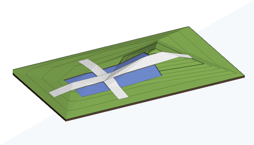
When creating a subdivision on a toposolid, a new sub-division is generated that follows the geometry of the host toposolid. You can provide an offset to the subdivision. A positive offset places the subdivision above the host, while a negative offset places it below the host. A negative offset excavates the host, and the excavation volume is reported in the properties of the subdivision. To create a subdivision that uses a different material than the host toposolid, change the toposolid type.
Subdivisions are a subcategory of toposolids. Use object styles and visibility/graphic overrides to control how subdivisions are displayed in views of your model.
- Inherit Contours - This is now controlled directly by the toposolid type used by the sub-division.
- Material - This is now controlled directly by the toposolid type used by the sub-division.
Layers used in compound structures such as a toposolid have a geometric limitation that must be greater than 0.8mm. If the original sub-division has a height less than 0.8mm, a type will be created with the minimum thickness. Graphically it will retain the height, position, and material of the original sub-division, and the bottom of the new sub-division will extend beneath the surface of the host toposolid.
For additional information, see Sub-divide a Toposolid.
Graded Region Volume Accuracy
The methods used to calculate the cut and fill volumes of a graded region have been revised for greater accuracy. Additional volumes beyond the boundary of the new toposolid are no longer included in the calculations. The volume is now calculated exclusively within the boundary of the new toposolid and projected upward.
For additional information, see Create a Graded Region and About Reporting Cut and Fill Volumes on a Site.
Improved accuracy when linking topography
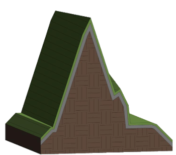
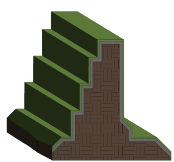
When reloading topography linked in previous releases of Revit LT, the improved precision of linking may result in topography that more closely aligns with the geometry of the link. In some cases, you can successfully link topography that was not previously possible. See images below for example.
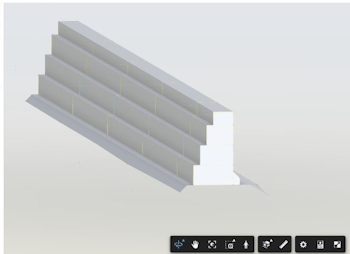
Source file to be linked
|
Before accuracy improvement | After accuracy improvement |
|---|---|
 |
 |
For additional information, see Link Topography.
Void Cut Stability
Enable Cut Void Stability in your models to increase the likelihood of successful cuts on some toposolids. The Cut Void Stability setting applies a small shift to the cut geometry at random along the x or y axis until a cut succeeds. The shift may slightly impact the accuracy of the void geometry. When Cut Void Stability is applied, any changes will be reported in a warning and in the journal file.
 These features were suggested by customers on the Ideas forum (Allow new topography sub-divisions to recess into topography and
Allow Toposolid subdivisions to use Toposolid Types (rather than just materials)) and are described on the
product road map.
These features were suggested by customers on the Ideas forum (Allow new topography sub-divisions to recess into topography and
Allow Toposolid subdivisions to use Toposolid Types (rather than just materials)) and are described on the
product road map.
For additional information, see Toposolid: Excavate and Remove Excavation.