 Constraint Editor
Scene > Constraint Editor
Video captions: Located in the main menu, the Constraint Editor lets you create Position, Orientation, Aim, and Parent Constraints using intuitive drag and drop functionalities. This capability ensures precise manipulation, enabling the creation of highly realistic and responsive animations and movements. You can create Position, Orientation, Aim, or Parent Constraints using the plus icon, the Create menu, or the right-click context menu.
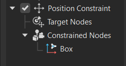
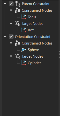
Constraints are made up of Target Nodes and a Constrained Node, and you can easily assign them by dragging objects from the Scenegraph or other modules.
For Aim Constraints, there’s also an Up Vector Node, just like in the Camera Editor.
In fact, any Cameras with Aim or Aim-and-Up created in the Camera Editor now show up as Aim Constraints — making them easy to adjust directly within the Constraint Editor.
Let’s take a closer look at the available constraint types.
The Position Constraint ensures that your object follows the position of one or more target objects — ideal for objects that need to move together or track each other dynamically.
The Orientation Constraint locks the rotation of an object so that it aligns with the orientation of its target. This is especially useful when syncing rotations between parts in a gear mechanism.
With the Aim Constraint, you can make an object continuously point towards a target — perfect for things like cameras, headlights, or tracking systems. You can also define an Up Vector to stabilize the object’s orientation and avoid unwanted flips.
The Parent Constraint allows an object to inherit translation, rotation, and scale from another — creating a parent-child relationship without altering the Scenegraph hierarchy. This gives you hierarchical behavior with full flexibility.
Constraints can use multiple target nodes, and each target can be weighted. This lets you control the influence each target has over the constrained object — useful for blending motions or creating weighted averages.
You can also assign multiple constrained nodes to a single target, allowing one object to drive the behavior of many others.
The editor lets you choose to maintain an offset, so constrained objects retain their relative position to the target — or you can disable it for direct inheritance.
And with scaling factors, you can even invert or multiply transformations — ideal for synchronized but mirrored motion, such as a gear rotation system.
Additionally, you can set object limits using the Transform Editor. This feature allows for quick and efficient limits in translation, rotation, or scaling along the X, Y, Z axes, enhancing control and accuracy, making complex setups more manageable.
Control the behavior and relationships between multiple objects in a scene with the Constraint Editor. Design intricate and dynamic animations and interactions without the need for programming expertise. Create a position, orientation, aim, or parent constraint, then drag and drop nodes you want constrained from the Scenegraph or their corresponding modules into the Constraint Editor.
If looking for Python commands for constraints, see vrConstraintService.
What Are Constraints?
Constraints apply a rule or limitation to an object or a set of objects, defining how they relate to each other and can move or be transformed. Constraints restrict an element's degree of freedom, ensuring it behaves predictably and maintains design intent, as the model is modified.
A constraint consists of the following:
Target object, which is what the constrained object is linked to.
Constrained object, which is the object whose properties are being controlled by the constraint. It's the object that will react to changes in the target object.
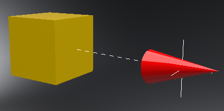
In the example below, the constraint links the properties of a target (the red button) to the constrained objects (the black buttons). The target's position controls the constrained objects. As demonstrated here, constraints can be applied to one or more objects within a model.
Constrained objects can be geometry, lights, cameras, and groups. Find a dashed line connected to any constrained objects and to the constraint selection handle, which is connected to the target object. VRED uses these to visually indicate the constraint relationship.
What Types of Constraints are in VRED?
VRED offers the following types of constraints:
 Position Constraint - Limits the movement (translation/position) of the constrained object to follow one or more target objects. Objects will remain in a specific position, when enabled to maintain the integrity and functionality of a design.
A position constraint consists of a target, which is used to fix an object to a specific coordinate, align it with another object, or maintain a certain distance between objects, and constrained node.
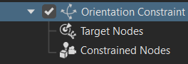
 Orientation Constraint - Limits the constrained object's rotation so it follows one or more target objects, aligning its axes with the target object's orientation. Use this to ensure components or elements maintain their intended angles, rotations, or alignments, which is essential for the proper functioning and assembly of a design.
An orientation constraint consists of a target that it is always oriented towards and constrained node.
 Aim Constraint - Directs the constrained object to always point toward a target object or point in space. This constraint is commonly used in animation to ensure objects, such as cameras, lights, or character eyes, maintain their focus on a particular target as it moves.
The aim constraint includes an up vector target node and target node, like an aim and up camera in the Camera Editor.
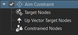
- Targets - The object or point the constrained object will always aim towards.
- Up Vector - Sets the up direction for the constrained object to ensure proper orientation. This prevents the object from flipping or rotating unexpectedly.
 Parent Constraint - Allows the constrained object to inherit the transformation properties (position, rotation, and scale) of the target parent object. This creates a parent-child relationship between objects, without actually placing them in a hierarchical structure within the Scenegraph. The constrained object (child) follows the movements and transformations of the target parent object, while still maintaining the ability to have its own adjustments.
The parent constraint include the following:
- Parent Object - The target object whose transformations are inherited by the constrained child object.
- Child Object - The constrained object that follows the transformations of the target parent object.
Parent constraints are useful in animation and rigging because they enable the creation of hierarchical relationships between objects, making it easier to manage complex movements and interactions. For example, in character animation, a hand can be constrained to a prop, ensuring it follows the prop's movements, while still allowing for additional hand animation.
About the Constraint Editor
![]() Menu Bar
Menu Bar
File
 Export Evaluation Sequence - Creates a .tgf file that can be opened in an online viewer to view and evaluate the constrained motion for debugging. Choose where the file will be stored.
Edit
Contains options for copying, pasting, merging, referencing, optimizing, removing, and locking/unlocking.
 Rename (Ctrl + R) - Renames the selected constraint.
 Copy (Ctrl + C) - Copies the selected constraint to the system clipboard.
 Paste (Ctrl + V) - Pastes a constraint saved on the clipboard into the constraint Group.
 Cut (Ctrl + X) - Removes the selected constraint, temporarily storing it on the clipboard.
 Duplicate (Ctrl + D) - Creates an independent copy of the selected constraint.
 Delete (Del) - Removes the selected constraint from the library when it's not in use.
 Remove Selected Assignment (Backspace) - Removes the selected geometry from the child node of the constraint. If the geometry is assigned to other constraints, those relationships are not affected.
Before Remove Selected Assignment After Remove Selected Assignment 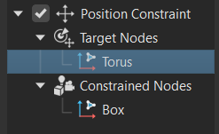
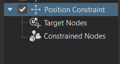
 Remove All Assignments - Removes all geometry assigned to a constraint. Select the top level of the constraint and click . Any geometry applied to its child nodes is removed, creating an empty constraint.
Before Remove All Assignment After Remove All Assignment 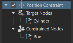
 Delete All Empty Constraints - Removes all empty constraints, cleaning up the constraint list tree.
Before Delete All Empty Constraints After Delete All Empty Constraints 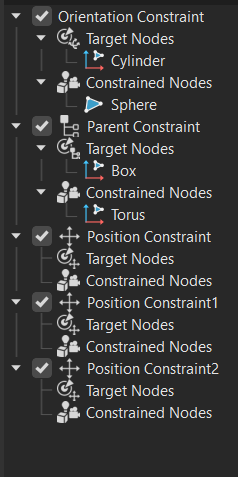
 Toggle Active / Inactive - Switches the state of the constraint. If active, it becomes inactive, and vice versa.
 Switch Active - Changes the state of an inactive constraint to active, applying the constained range.
 Switch Inactive - Changes the state of an active constraint to inactive, not applying the constained range.
Create
Create Constraints - Provides different constaints to choose from, such as Position Constraint, Orientation Constraint, Aim Constraint, and Parent Constraint. Each type consists of a target and constrained node. See Available Constraints in VRED to learn about each of these constraints.
 Create Group (Ctrl + G) - Creates a node for grouping constraints, which can be combined into any number of combinations, such as groups inside groups. Once created, drag and drop content from the Constraint list tree into the group.
Selection
Contains options for dealing with selecting things within a scene.
Select Objects In - Choose where the active objects will be selected.
 All Editors (Ctrl + N) - Selects the active nodes in the Camera Editor, Light Editor, and Scenegraph, if open.
- Scenegraph - Selects the active nodes in the Scenegraph, if open.
 Camera Editor - Selects the active nodes in the Camera Editor, if open.
 Light Editor - Selects the active nodes in the Light Editor, if open.
 Select All (Ctrl + A) - Selects all constraints.
 Deselect All (Ctrl + Shift + A) - Deselects all constraints.
 Invert Selection (Ctrl + I) - Switches from what is selected to everything that was not selected.
 Group Selection (Ctrl + Shift + G) - Creates a group from the selected constraint.
![]() Toolbar
Toolbar
 Create Constraints - Select the type of constraint created from its menu. Choose from: Position Constraint, Orientation Constraint, Aim Constraint, and Parent Constraint. See Available Constraints in VRED to learn about each of these constraints.
- Duplicate (Ctrl + D) - Creates an independent copy of the selected constraint.
- Delete (Del) - Removes the selected constraint from the library when it's not in use.
- Create Group (Ctrl + G) - Creates a node for grouping nodes. Once created, drag and drop content into it.
- All Editors (Ctrl + N) - Opens the Camera Editor, Light Editor and Scenegraph.
- Remove Selected Assignment (Backspace) - See Remove Selected Assignment in the Menu Bar section.
- Remove All Assignments - See Remove All Assignment in the Menu Bar section.
- Delete All Empty Constraints - See Delete All Empty Constraints in the Menu Bar section.
![]() Search and Filtering
Search and Filtering
The Constraint Editor has a basic search and filtering.
 Basic Search
The search bar provides live-search capabilities for constraints. It is helpful for quickly identifying constraints in complex scenes without browsing through a vast constraint list. Search using a single letter or search term. Note that only single search terms and regular expressions are supported. Entering one character shows only constraints containing the character.
Right-clicking within the search bar provides a context menu with undo, redo, cut, copy, paste, delete, and select all options.
When used with ![]() Filter Search Depth, the search goes from being a top-level search of only parent constraints and groups, to a more thorough deep hierarchy search.
Filter Search Depth, the search goes from being a top-level search of only parent constraints and groups, to a more thorough deep hierarchy search.
 Filter Search Depth
Use ![]() Filter Search Depth to toggle between flat and recursive matches. When disabled, only top-level matches appear. When enabled, matches deeper in the hierarchy appear.
Filter Search Depth to toggle between flat and recursive matches. When disabled, only top-level matches appear. When enabled, matches deeper in the hierarchy appear.
 Filtering
Use ![]() to toggle filtering on or off and access the Filter Selection menu for configuring the filter settings.
to toggle filtering on or off and access the Filter Selection menu for configuring the filter settings.
 filtering is off. Click to enable filtering.
 filtering is on. Click to disable filtering.
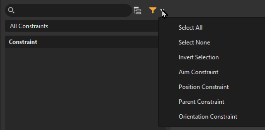
Press-hold ![]() to access the Filter Selection menu for configuring the filter settings. Use it to filter by constraint type, toggle between different things, select all, invert the selection, or clear the selection/filtering. Use these options in conjunction with a search term and search depth
to access the Filter Selection menu for configuring the filter settings. Use it to filter by constraint type, toggle between different things, select all, invert the selection, or clear the selection/filtering. Use these options in conjunction with a search term and search depth ![]() to further define a search.
to further define a search.
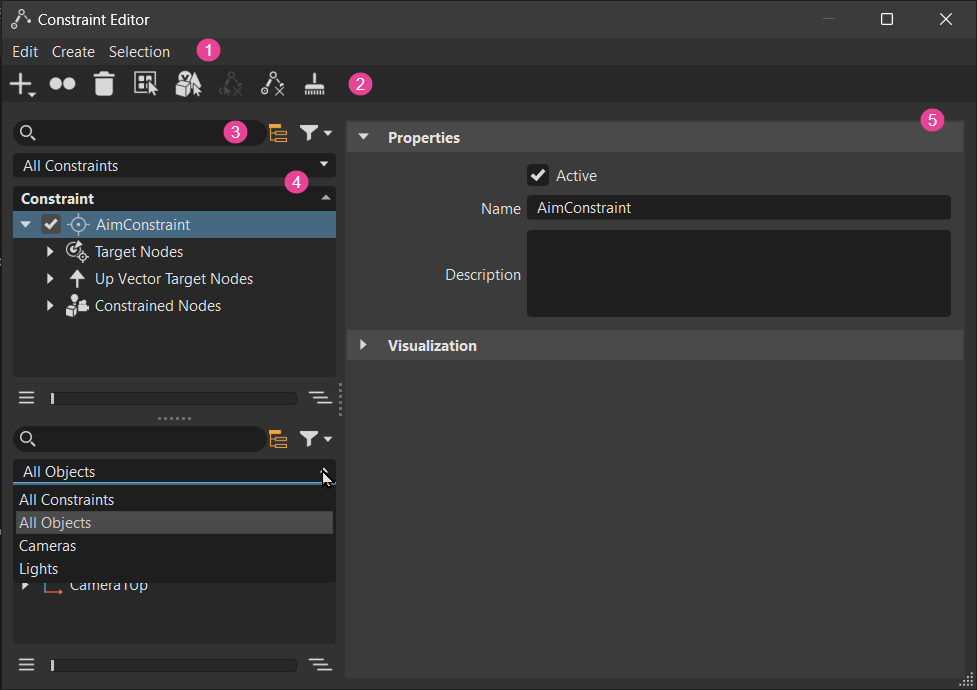
![]() Constraint Lister
Constraint Lister
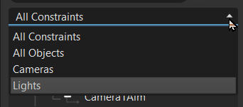
The content displayed in the Constraint Lister is defined by search and filtering and the dropdown menu in this section. Use the dropdown menu to further define the content by choosing from displaying all constraints, all objects, only cameras, or only lights.
Right-click to access the Constraint Lister context menu, containing options found in the menu bar.
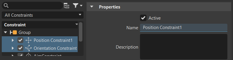
Selecting an element in the Constraint Lister selects it in its editor, displays it in the scene, and loads its settings into the Attributes. If multiple elements are selected, any fields highlighted blue indicate unique settings for that field. In the case below, there are two unique names.
Split View
Work with two views by dragging the handle at the bottom of the lister to expose a second one. The search and filtering tools act only on their view. Use it to add a constraint into a group or to another constraint for creating more complex workflows.
Slider
The slider and its buttons are a fast way to expand or collapse the sub-structure of the selection or multi-selection. With nothing selected, all nodes are expanded.
Click ![]() to collapse the hierarchy of the selected node or
to collapse the hierarchy of the selected node or ![]() to expand it.
to expand it.
![]() Attributes
Attributes
Properties
When the top node of a constraint is selected, these options appear to determine whether the constraint is used and provides a means for identifying it and its function.
Active - Sets the constraint as active or inactive. When active, VRED restricts the range of motion to that of the constraint. When inactive, the range of motion is ignored and not restricted.
Name - Displays the name of the selected constraint. Use this field for edit the name.
Description - Provides a description of what the constraint does. For example, "This gear example illustrates how rotations can be transferred between objects, considering the need for acceleration, deceleration, or inversion." Use the
 to modify the text and to delete the description.
Visualization
These options determine if constraint visualizations, such as the dashed line and handles, are displayed and their size.
Show Constraint - Displays or hides the dashed line connecting the constraint object and target, as well as the constraint handles. Use Scale to change the size of the handles.
Scale - Sets the size of the contraint handles. Increasing the number increases the constraint size for easier selection in the scene.
Scale = 1000 Scale = 2000 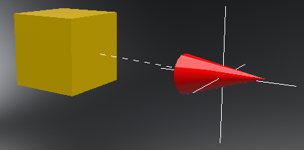
Alignment
Only available for Aim Constraint > Constrainted Nodes objects.
Aim - Sets the camera aim orientation to always point it towards a target object.
Up - Sets the camera up direction, ensuring proper orientation.
Use Rotation Orientation - Controls how an object rotates by defining the pivot around which the rotation occurs, and then constraining that rotation to a specific axis. This enables precise control over how objects animate or are manipulated, ensuring they rotate naturally and as intended.
Up Vector Target
Only available for Aim Constraint > Up Vector Target Nodes objects.
- Weight - Each target can have a different weight, so use this to influence how much the target affects the constrained object’s position.
Constraint Target
Only available for Target Nodes objects.
- Weight - Sets the weight for a target object of the constraint. Each target can have a different weight, influencing how much it affects the constrained object’s position.
Offset
Use Maintained Offset - Maintains an offset between the constrained and target object, enabling the constrained object to follow the target, while keeping a specific distance, rotation, and/or scale. This is the default (enabled) and this offset is set before the objects are constrained.
Tip:With large data sets, this option should be enabled, as existing offsets will not be changed. However, for new imported data, having this disabled might be useful if offsets need to be finely adjusted.
However, if Use Maintained Offset is disabled, the constraint object inherits the position, rotation, and/or scale of the target object. This results in the constraint object appearing over the target. Use the following offset X, Y, Z options to manually set the offset.
Rotation Offset - Only available for orientation and parent constraints. Manually sets how much the constraint rotation is offset along the X, Y, and Z axes. Define these by using red for X, green for Y, and blue for Z.
Translation Offset - Only available for position and parent constraints. Manually sets how much the constraint translation is offset along the X, Y, and Z axes. Define these by using red for X, green for Y, and blue for Z.
Scale Offset - Only available for parent constraints. Manually sets how much the constraint rotation is offset along the X, Y, and Z axes. Define these by using red for X, green for Y, and blue for Z.
Apply Transformation
From Target - Specifies the type of transformation applied from the target object. Choose from:
Object - Uses the coordinate system from an object’s point of view, with the object’s pivot point being the origin. Object space is used to set the position of an object relative to its pivot point.
World - Uses the coordinate system of the entire scene. All objects are placed in a 3D universe defined by their coordinates relative to the center of the scene.
To Constrained - Specifies the type of transformation applied to the constrained object. Choose from:
Object - Uses the coordinate system from an object’s point of view, with the object’s pivot point being the origin. Object space is used to set the position of an object relative to its pivot point.
World - Uses the coordinate system of the entire scene. All objects are placed in a 3D universe defined by their coordinates relative to the center of the scene.
Uniform Scaling Factor - Sets the same X, Y, and Z scaling for the speed of the constrained motion, when enabled. When disabled, different values can be set for X, Y, and Z using the Scaling Factor fields.
Scaling Factor - Changes the speed of the constrained motion.
Note:Scaling Factor changes must occur on the same axis as the target for changes in speed to occur. If a Scaling Factor value is set for a different axis than the one the target is moving along, there is no change.
A value of 1, matches the speed of the constrained object with the target.
Large values, whether positive or negative, multiply the transformation applied to a constrained object along that axis, making it move faster than the target and eventually overtaking it.
Small values slow the motion, causing the constrained object to move slower than the target and eventually lag behind. This can be especially helpful when translations or rotation directions change, as seen in a gear mechanism.
 Note:
Note:To set different X, Y, and Z scaling factor values, disable Uniform Scaling Factor.