Constraint Editor
Control the behavior and relationships between multiple objects in a scene with the new Constraint Editor. Design intricate and dynamic animations and interactions without the need for programming expertise. Create a position, orientation, aim, or parent constraint, then drag and drop nodes you want constrained from the Scenegraph or their corresponding modules into the Constraint Editor.
Video captions: Located in the main menu, the Constraint Editor lets you create Position, Orientation, Aim, and Parent Constraints using intuitive drag and drop functionalities. This capability ensures precise manipulation, enabling the creation of highly realistic and responsive animations and movements. You can create Position, Orientation, Aim, or Parent Constraints using the plus icon, the Create menu, or the right-click context menu.
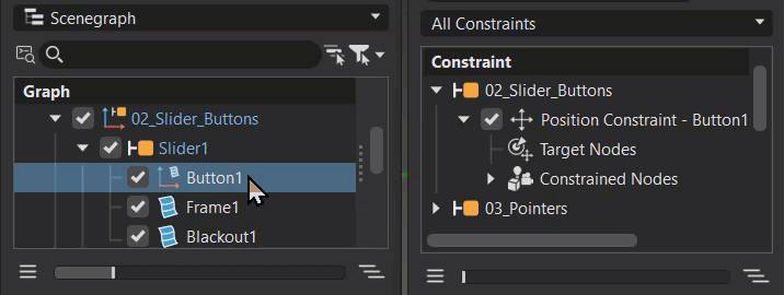
Constraints are made up of Target Nodes and a Constrained Node, and you can easily assign them by dragging objects from the Scenegraph or other modules.
For Aim Constraints, there’s also an Up Vector Node, just like in the Camera Editor.
In fact, any Cameras with Aim or Aim-and-Up created in the Camera Editor now show up as Aim Constraints — making them easy to adjust directly within the Constraint Editor.
Let’s take a closer look at the available constraint types.
The Position Constraint ensures that your object follows the position of one or more target objects — ideal for objects that need to move together or track each other dynamically.
The Orientation Constraint locks the rotation of an object so that it aligns with the orientation of its target. This is especially useful when syncing rotations between parts in a gear mechanism.
With the Aim Constraint, you can make an object continuously point towards a target — perfect for things like cameras, headlights, or tracking systems. You can also define an Up Vector to stabilize the object’s orientation and avoid unwanted flips.
The Parent Constraint allows an object to inherit translation, rotation, and scale from another — creating a parent-child relationship without altering the Scenegraph hierarchy. This gives you hierarchical behavior with full flexibility.
Constraints can use multiple target nodes, and each target can be weighted. This lets you control the influence each target has over the constrained object — useful for blending motions or creating weighted averages.
You can also assign multiple constrained nodes to a single target, allowing one object to drive the behavior of many others.
The editor lets you choose to maintain an offset, so constrained objects retain their relative position to the target — or you can disable it for direct inheritance.
And with scaling factors, you can even invert or multiply transformations — ideal for synchronized but mirrored motion, such as a gear rotation system.
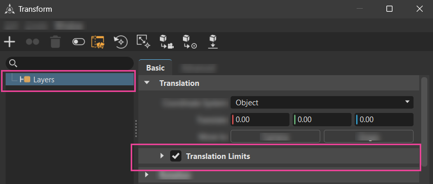
Additionally, you can set object limits using the Transform Editor. This feature allows for quick and efficient limits in translation, rotation, or scaling along the X, Y, Z axes, enhancing control and accuracy, making complex setups more manageable.
For additional information on constraints, see the following:
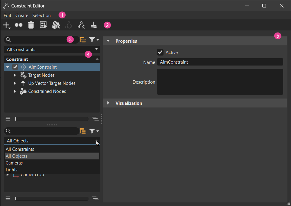
The Constraint Editor consists of the following:
 A menu bar for finding tools to export evaluation sequences and create, edit, and select constraints.
 A toolbar for quickly accessing frequently used tools.
 A basic search and filtering for quickly locating specific content.
 A Constraint Lister for a way to visually organize and navigate constraint content. Expand and collapse nodes to find a specific item quickly. Use the Constraint Lister dropdown with the basic search and filtering to further refine a search. And, for quick and convenient access to tools, use the right-click context menu.
 An Attributes panel for activating/deactivating a constraint, adding a description, showing or hiding a constraint in the viewport, setting weights, and more. See Attributes for additional information on these.
To see how constraints work and are set up, check out the example scene file at File > Open Examples, open constraint_example.vpb, then select Animation > Timeline to display the animation timeline and press ![]() .
.
Creating a Constraint
Use ![]() and choose the type of constraint to create. When a constraint is created, it is added to the Constraint Lister and its attributes, which can be adjusted, are loaded into the panel to the right. Drag nodes from the Scenegraph or other editors onto the target and constrained nodes to create constaint relationships.
and choose the type of constraint to create. When a constraint is created, it is added to the Constraint Lister and its attributes, which can be adjusted, are loaded into the panel to the right. Drag nodes from the Scenegraph or other editors onto the target and constrained nodes to create constaint relationships.
Click
 and choose the type of constraint to create.
In the Constraint Lister, expand the new constraint.
Drag one or more nodes from the Scenegraph or other editors onto the Target Nodes node to create a target object. Drag another node onto the Constrained Nodes node to create a constrained object.
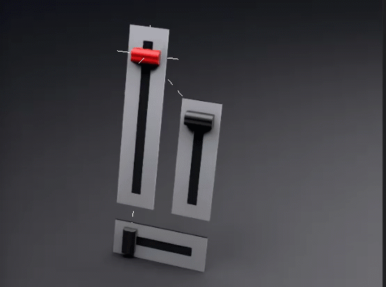
Now, if you move the target object (the red lever), the constrained object(s) follow.
(Optional) In the Constraint Lister, select the parent of the Target and Constrained Nodes to modify its settings. It can be set as active or not, renamed, and a description can be added. Determine whether the constraint handles are visible and their size. Select the dragged object node to make changes to the weighting.
Selecting a Constraint
The constraint handle can be selected in the viewport using Shift + LMB, but it must be visible and large enough to select. You can also right-click the constraint node and select Select Objects In > Scenegraph from the context menu. When a constraint handle is selected, its targets are selected and highlighted yellow in the viewport. In the Scenegraph and Constraint Editor (if open), their nodes will be selected and highlighted blue.
In the toolbar, ensure Transform and Boundings are enabled.
In the Constraint Editor, expand the parent node and select a constraint node. In the example, the
Arrowsfolder was expanded andOrientation Constraintnode is selected.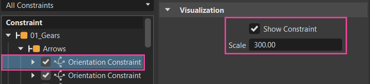
Ensure Show Constraint is checked and increase Scale to a larger value, such as 300, to easily see and select the constraint handle.
Scale = 100 Scale = 300 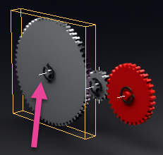
Now, either Shift + LMB the constraint handle to select it or right-click the constraint node and select Select Objects In > Scenegraph.
Saving a Constraint
When constraints are created and the scene is saved as a .vpb, using File > Save or Save As, they are preserved in geometry assets and work as expected when reloaded into a scene.
Constraining a Clipping Plane
To set up a constrained and movable clipping plane, use a World-to-Local approach. This calculates the world transformation, yet applies the constraint locally to the clipping plane. This ensures the clipping plane is constrained to another node, using a parent constraint, and can move.
In the Constraint Editor, once a constraint is created, expand it to expose the Constrained Nodes node.
In the Scenegraph, drag and drop a clipping plane onto Constrained Nodes in the Constraint Editor.
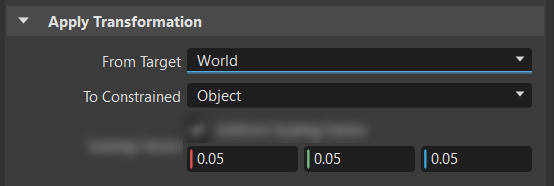
In the Constraint Editor, select the clipping plane, then in the Apply Transformation attributes section, set From Target to World and To Constrained to Object.
Undoing Constraint Creation and Deletion
Through the UI, a constraint cannot be uncreated or undeleted. However, using Python, constraints can be uncreated and undeleted with vrConstraintService.
Exporting an Evaluation Sequence
Export all constraints applied to scene to a single constraints file, using Export Evaluation Sequence. Use this file, for example, to share, reorder, and enable/disable constaints within a constraint set. This file can be shared with others.
- Select File > Export Evaluation Sequence.
- In the browser, set where the evaluation sequence file (.tgf) will be stored.
- Click Save.
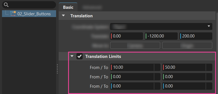
Setting Limits
We've added Translation, Rotation, and Scaling Limits to the Transform Editor for aiming constraints and Translation Limits and Rotation Limits to the Camera Editor > Camera Settings > Viewing section for limiting the movement of cameras. These enable limits to be set on the movement, rotation, and scaling of a target, restricting its transformation to the ranges set. Though you can use these alongside constraints, they are not mandatory to restrict the target or constraint node. Quickly limit the translation, rotation, and scaling along the X, Y, and Z axes by defining these with the From/To limits. Red is X, green is Y, and blue is Z.
In the Scenegraph, use the Expansion Column to identify nodes with limits (![]() ).
).
Double-clicking the icon opens the Transform Editor with the node selected and the limits section visible.
To Limit an Object Node
In the Scenegraph, select the node to limit.
In the Quick Access Bar, select Transform to open the Transform Editor.
With the node selected in the Transform Editor, in the Basic tab of the Attributes, expand the section to limit transformations. For example, expand the Translation section.
Click the box in front of the limits section to enable it, then expand the section and set the limits.
To Limit a Camera Node
- In the Scenegraph, select the camera node to limit.
- In the Quick Access Bar, select Cameras to open the Camera Editor.
- With the camera node selected in the Camera Editor, in the Camera Settings tab of the Attributes, expand the Viewing section to access the Translation and Rotations Limits sections.
- Click the box in front of these section to enable them, then expand the sections and set the limits.