The geometry of network objects can be edited on the GeoPlan window, the network object grid views, or the property sheets.
This topic also describes the tools available to adjust the coordinates of a selection of objects.
To edit the geometry of a network object on the GeoPlan
- Click the
 (Edit object geometry) button on the
Tools toolbar to turn on
edit object geometry mode.
- Click the object to be edited in the GeoPlan.
Details on how to edit the different object types are given below.
Moving nodes, customer points, or spatial data items
- Using the Edit Geometry tool, click the node, customer point, or spatial data item you want to move. The object turns red to indicate that it is selected.
- Click the object again, hold down the mouse button and move the cursor to place the object to its new position. Release the mouse button to complete the move.
Moving links
To move a link, you must move the nodes at one or both ends. However, you can move the internal bends in a link.
Moving bends in links
Links in the model can have bends on the GeoPlan window so they can more closely follow their actual physical position when building a geographically accurate model.
If your link uses the default (#D) flag for its length field, the bends are taken into account when calculating the length from the GeoPlan coordinates. Otherwise, bends are purely for modelling convenience, and have no effect on computation.
- Click the link you want to edit.
Intermediate points are shown as red squares.
- To add an intermediate point press Ctrl and click.
- To remove an intermediate point press Alt and click.
- To move an intermediate point click and drag with the mouse button held down.
Polygon or polyline objects can be edited by
- moving vertices
- adding or deleting vertices
- snapping vertices to vertices on other polygons or polylines, and unsnapping the vertices if needed
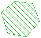
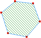
A polygon or polyline is made up of a series of vertices and edges. To edit an object it must be highlighted using the appropriate tool. This highlights the vertices (the points that can be changed) in red.
See the Polygon and Polyline Objects topic for a list of appropriate editing tools for each type of polygon and polyline.
Individual object types may have specific editing issues. Refer to the help for these objects for more information.
|
Polygon made up of vertices and edges |
When highlighted for editing, the vertices are displayed in red |
When the object has been edited, click another polygon or polyline for editing, or click the
 toolbar button (pressing the Esc key has the same effect) to return to the default selection mode.
Moving a vertex
- with snapping mode on, all snapped vertices are moved together
- with snapping mode off, all vertices are treated as being independent; only the vertex from the currently highlighted polyline or polygon will be moved.
A vertex can be moved by dragging it to a new location. If two or more vertices are snapped together, the behaviour varies depending on whether snapping mode is switched on:
To move a vertex of a polygon or polyline object
- Click the object.
- Move the cursor over the vertex to be moved. A cross will appear over the vertex when the cursor is locked on that point .

- To reshape the polygon or polyline, hold down the left mouse button and move the mouse to drag the vertex to a new position.
To add a vertex to a polygon or polyline object
- Click the object.
- Move the
 cursor over the edge of the polygon or polyline to which a new vertex is to be added.
- To add a new vertex, hold down the Ctrl key and click the left mouse button.
Deleting a vertex
- Click the object.
- Move the
 cursor over the vertex to be deleted. A cross will appear over the vertex when the cursor is locked on that point.

- Hold down the Alt key and click the left mouse button to delete the vertex.
Vertices can be deleted from polygon or polyline objects. However, polygons must have a minimum of three vertices. Also the two end points of a polyline cannot be deleted.
To delete a vertex from a polygon or polyline object:
To snap two points together
- Ensure that snapping mode is switched on.
- Click the object whose vertex you want to move.
- Move the cursor over the vertex to be moved. A cross will appear over the vertex when the cursor is locked on that point.

- Hold down the left mouse button and move the mouse to drag the vertex. When close enough to another vertex to snap the points together, a cross is drawn on the vertex you are moving towards.
- Release the mouse button to snap the two points together.
Vertices from different polygon and polyline objects can be snapped together. Once the two objects are snapped together, the shared vertices can be moved as if they are a single vertex as long as snapping mode is switched on.
Unsnapping vertices
To unsnap vertices, switch off snapping mode.
With snapping mode off, all vertices are treated as being independent, even if they share the same location. When moving or deleting a vertex, only the vertex in the polygon or polyline currently highlighted will be edited.
You can change the shape of any polygon from the GeoPlan window:
- Click inside an existing polygon. The polygon borders are shown in blue and the corner points are displayed in red.
- Drag any of the corner points to new positions to reshape the polygon. When you start dragging, the cursor may disappear. The moving edges of the polygon are shown in red.
- To add a new corner point to the polygon border, hold down the Ctrl key and click the border. You can then move this new corner as described above.
- When you have finished reshaping the polygon, click another polygon or click the
 toolbar icon to return to the default selection mode.
To move a selection of network objects
- Select the objects to be moved.
- Select Selection
 Selection operations
  Geographically adjust selection.
The Geographical Adjustment of Selection dialog is displayed.
You can change the scale for the X or Y co-ordinates or move items relative to their current position.
- When you have made the changes, click OK.
You can change the position of any selection of network objects. When you move a node, the positions of any links attached to the node are also updated.
To reverse the direction of a selection of links
- Select the links to be reversed.
- From the
Selection menu, choose
Selection operations | Reverse links or click the link reversal tool
 .
.
The operation only switches the upstream and downstream nodes. It makes no other changes to the link.
Editing object geometry on the network grids or property sheets
X and Y coordinates for nodes can be edited by typing or pasting new values into the grid or property sheet. The grid data manipulation tools - Adjust Cell Value and New Cell Value - may also be used to adjust coordinates for a group of nodes. See Editing data in the network object grid views for more information.

