Learn how you can configure drawing styles to display a hole using a symbol instead of its real shape from the model using the Management Tools application and a series of DWG files containing the shapes that make up the symbol.
This symbol can be configured using a series of DWG files that store its shape made from AutoCAD lines, which are then assigned to a specific hole diameter or a series of identical holes of a given type.
The elements in the symbol representation (dwg storing the symbol which are to be exactly correlated with the hole diameters in the drawing) must be exactly 10 units in size and be centered in the drawing WCS origin.
In order to start configuring a hole symbol, you need to access the AstorBase database  Symbols table. To do this:
- Open the Management Tools application, from the Home tab Settings panel
 (Management Tools).
- In the Management Tools application, access the Table editor.
- In the top left corner of the Table editor, click on the second icon to open a database.
- The Open dialog appears. Choose the AstorBase.mdf database file and click Open.
- Once the AstorBase.mdf is loaded, expand the heading (by clicking on the arrow next to the database name) and navigate to the Symbols table - alternatively, you can type the word "Symbols" in the Use filter search field to access the table more easily.
- In the Symbols table, go to the last filled row and configure a new one after it.
Configure the Key and Name columns
- For the Key column, use any number that is unique in this table.
- The Name column should contain a string created with the following format, that configures a specific hole symbol with the hole diameter, hole type, view direction and visibility status:
hole_ [DIAMETER]_[HOLE_TYPE]_[VIEWDIRECTION]_[VISIBILITYSTATUS].
- [DIAMETER] the hole diameter can have any numerical specific value or it can be set to Any.
- [HOLE_TYPE] the hole type can be set to any of the current specific available hole types or it can be set to Any. The available hole types are:
- Hole
- Slotted
- CounterSunk
- Blind
- Thread
- SunkBolt
- PunchMark
- [VIEWDIRECTION] the direction of the view (the geometric restriction of the hole) can have the following values:
- Fr the hole is seen from the front.
- To the holes are seen from the top (the z-axis of the hole is the same as the z direction of the view).
- Bo the holes are seen from the bottom (the z-axis of the holes is in the opposite direction of the z direction of the view).
- ToBo the holes are seen from the top or the bottom.
Note: The search for a corresponding symbol is done using the following priorities, regarding the view direction (To, Bo and ToBo): first the search is done for a symbol with an exact view direction (Top or Bottom). If a corresponding symbol is not found for the first case - no symbol is configured for the specific top or bottom view directions, the search continues for a symbol with the ToBo view direction. - Fr
- [VISIBILITYSTATUS] the hole visibility status in the drawing:
- V the hole is visible.
- H the hole is hidden.
- VH the hole is visible and/or hidden.
Note: The search for a corresponding symbol is done using the following priorities: first the search is done for a specific status of the hole, either visible or hidden. If a corresponding symbol is not found for the first case, the search continues for a symbol with the VH (Any) visibility status. - V
- [DIAMETER]
Examples:
hole_Any_Slotted_ToBo_VH - all diameters for slotted holes, with a top / bottom view direction and a VisibleHidden visibility status.
hole_26_Any_Fr_H - any type of hole with the diameter equal to 26, viewed from the front and with a Hidden visibility status.
Drawing name association
The elements in the symbol representation must be exactly 10 units in size and be centered in the drawing WCS origin. In order to use such a symbol DWG file, you need to store it in the following folder: ...\ProgramData\Autodesk\Advance Steel 2026\[INSTALLATION LANGUAGE EXTENSION]\Shared\Support\Symbols.
There are two hole symbol configuration cases:
- To, Bo or ToBo symbols: The symbol is created in one part (DWG file). In the Symbols table, the file name is stored in the DwgName1 column corresponding to the respective hole name configuration, in the filename.dwg form. The Scale1, Translation1 and Rotation1 columns remain with a 0 value.
- Fr symbol: This symbol is defined using the following rules:
- The symbol is created from three parts (DWG files):
- The middle part that corresponds to the hole body.
- The top part that corresponds to the "exit" of the z-axis of the hole.
- The bottom part that corresponds to the opposite side of the z-axis of the hole.
- The middle part of the symbol is "scaled" in order to have the correct height (which is based on its length, the actual "system" representation of the hole).
- The columns used for these three parts are the following:
- Top part: DwgName1.
- Middle part: DwgName2.
- Bottom part: DwgName3.
In addition, the component parts of the hole symbol are identified by their Scale value: For the top part, the scale value must be "-1", for the middle part "-2" and for the bottom part "-3".
If the scale is not specified, the drawing will not be used for symbol creation.
- The symbol is created from three parts (DWG files):
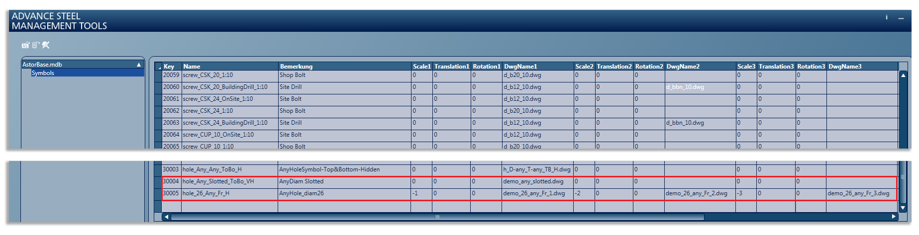
This is how the two example hole symbol configuration lines appear in the Symbols table: