Path Constraint
Use the Path constraint to restrict an object's movement along a spline or at an averaged distance among multiple splines.
- Assign Controller (object Position track) > Path Constraint
- Default menu: Animation menu > Position Controllers > Path Constraint
- Alt menu: Animation menu > Constraints > Path Constraint
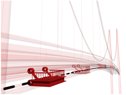
Path constraint positions the service platform along the side of the bridge.
A path target can be any type of spline. The spline curve (target) defines a path of motion for the constrained object. Targets can be animated using any of the standard translation, rotation, scale tools. Setting keys at a sub-object level of the path, such as vertex or segment, animates the path while affecting the constrained object.
Multiple Targets and Weighting
A constrained object can be influenced by several target objects. When using multiple targets, each target has a weight value that defines the degree by which it influences the constrained object, relative to other targets.
Using Weight is meaningful (and available) only with multiple targets. A value of 0 means the target has no influence. Any value greater than 0 causes the target to influence the constrained object relative to other targets' Weight settings. For example, a target with a Weight value of 80 will have twice the influence of a target with a Weight value of 40.
Procedures
To assign a Path constraint:
Create a Sphere with a radius of 10 and a Circle with a radius of 60.
With the Sphere selected, choose Animation menu > Constraints > Path Constraint.
You are now in select target mode, as indicated by the rubber-band line attached to the mouse cursor.
In the viewport, click the Circle shape.
To access the Path constraint’s parameters through the Motion panel:
 Select the Sphere.
Open the
 Motion panel.
In the PRS Parameters rollout, click the Position button.
The Path constraint's settings are located in the Path Parameters rollout.
Example: To assign a Path constraint through the Motion panel:
- Create a Sphere with a radius of 10 and a Circle with a radius of 60.
- Select the Sphere.
- Go to the Motion panel and click Parameters.
- Open the Assign Controller rollout and select the Position controller.
- Click
 (Assign Controller).
 - Choose Path Constraint from the Assign Position Controller dialog.
- On the Motion panel, click Parameters.
- In the Path Parameters rollout, click Add Path.
- In the viewport, click the Circle.
To edit weight values:
On the
 Create panel, click
  (Shapes), and create a Line that is about 120 units long.Tip: Use the diameter of the Circle to gauge the length of the Line.
- Select the Sphere.
On the
Motion panel, open the Path Parameters rollout.Click the Add Path button, then click the line.
The Sphere is now affected equally by both paths since the path weighting defaults to 50
Adjust the Weight spinner or enter a numerical value for the weight value.
Example continued: To animate weight values:
- Select the Sphere.
- On the Motion panel, open the Path Parameters rollout.
- Turn on
 .
. - Select Line01 from the Path list.
- Drag the time slider to frame 50 and change the Weight of Line01 to 75.
- Drag the time slider at frame 100 and change the Weight of Line01 to 10.
- Select the Circle01 path and change its Weighting to 25.
- Turn off
 and
and  play the animation.
To correct path constrained object flipping:
When an object is assigned a path constraint and the follow box is turned on, the object will rotate as it moves along the path. Sometimes the object is subject to unwanted flipping.
- Select the object that is flipping.
- On the Animation menu choose Constraints > Orientation constraint, then constrain the object to another object's orientation.
- Use the control object to adjust the flipping. Animate the orientation of the control object, while watching the flipped object at the problematic frames.
Interface
Path Parameters rollout
Once you assign a Path constraint, you can access its properties on the Motion panel > Path Parameters rollout. On this rollout you can add or delete targets, assign weighting, and animate each target's weight value.
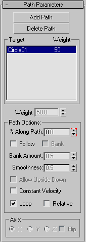
Add Path
Adds a new spline path that influences the constrained object.
Delete path
Removes a path from the target list. Once removing the path target, it will no longer influence the constrained object
[path list]
Shows the paths and their weights.
Weight
Assigns and animates weight values for each target.
Path Options group
% Along Path
Sets the percent that the object is positioned along the path. This duplicates the Value spinner in the track Properties dialog for the Percent track in Track View. If you want to set keys to place an object at a certain percent along the path, turn on Auto Key, move to the frame where you want the key set, and adjust the % Along Path spinner to move the object.
Follow
Aligns the object to the trajectory as it follows the contour.
Bank
Allows the object to bank (roll) as it negotiates the curves of the spline.
Bank Amount
Adjusts the amount of the banking to one side or the other, depending on whether the value is positive or negative.
Smoothness
Controls how rapidly the roll angle changes as the object moves through bends in the trajectory. Smaller values will make the object more responsive to subtle changes in the curve, while larger values smooth out jerking. The default value is a good value for general damping along the curve. Values below 2 tend to make the action jerky, but values around 3 can be very useful for simulating a certain degree of realistic instability.
Allow Upside Down
Turn on to avoid the situation in which an object flips when going around a vertically oriented path.
Constant Velocity
Provides a constant velocity along the path. When off, the velocity of the object along the path varies depending on the distance between the vertices on the path.
Loop
By default, when the constrained object reaches the end of a path it can no longer move past the end point. The loop option changes this behavior so that when the constrained object reaches the end of the path it loops back to the starting point.
Relative
Turn on to maintain the original position of the constrained object. The object will follow the path with an offset distance based on its original world space position.
Axis group
X/Y/Z
Defines which axis of the object is aligned to the trajectory of the path.
Flip
Turn on to flip the direction of the axis.
Path Joint rollout
The following controls are located on the  Hierarchy panel while the IK button is active:
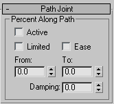
Active
Activates an axis (X/Y/Z). Allows the selected object to animate along the activated path.
Limited
Limits the range of motion allowed on an active path. Use in conjunction with the From and To spinners.
Ease
Causes a joint to resist motion as it approaches its From and To limits. Simulates an organic joint, or worn mechanical joint, moving or rotating freely in the middle of its range of motion but moving less freely at the extremes of its range.
From and To Spinners
Determine for path limits. Use in conjunction with the Limited function.
Damping
Applies resistance over a joint's motion along the path. Simulates the natural effect of joint friction or inertia.