Use this tab to reference the baseline information for the channel.
Use this tab to reference the baseline information for the channel.
Baseline
Feature Line. Displays the name of the feature line referenced for the baseline. Displays as NA if Alignment/profile baseline is selected.
Alignment. Displays the name of the alignment referenced for the baseline. Displays as NA if Feature line baseline is selected.
Profile. Displays the name of the profile associated with the alignment referenced for the baseline. Displays as NA if Feature line baseline is selected.
Define a station range. Enables stationing along the channel.
Start Station.
Specifies the starting station for the channel. Click
 to manually select a station location in the drawing.
End Station.
Specifies the ending station for the channel. Click
to manually select a station location in the drawing.
General
As Defined. Enables the automatic creation of channel segments based on changes in grade along the baseline.
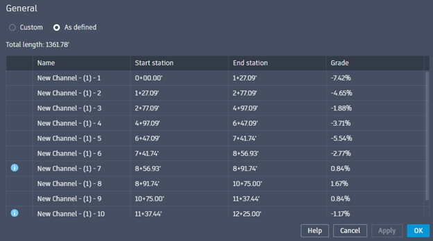
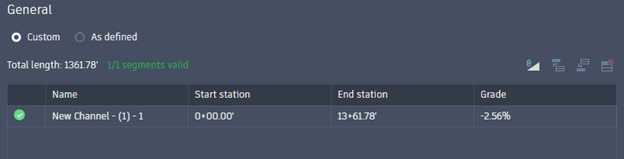
Total Length. Displays the total linear length of the baseline.
Name. Displays the name of each channel segment. This adds a numerical suffix to the channel name and is read-only.
Start Station. Displays the start station of each channel segment. This value should be within the defined station range or an error will be displayed.
End Station. Displays the end station of each channel segment. This value should be within the defined station range or an error will be displayed.
Grade. Displays the grade of each channel segment. This is represented as a percent grade and will read Horizontal if no slope exists. A negative grade represents a downward slope along the stationing.
Custom Option Tools. The following tools are available when using the Custom option.
- Import from automatically calculated slopes. This will overwrite any customized slope data with auto-calculated data. The user will then be able to adjust the auto-calculated data.
- Insert row above. This option splits the station range for the current row and adds a row above. A station value must be entered to define the location of the split.
- Insert row below. This option splits the station range for the current row and adds a row below. A station value must be entered to define the location of the split.
- Delete selected row. This will delete the current station range by combining it with the row below. If the last row is deleted it is combined with the row above. If there is only one row, it cannot be deleted.
Longitudinal Slope. Displays the slope of the baseline. This is represented as rise:run and will read Horizontal if no slope exists.
Length. Displays the linear length of the baseline.