Use this tab to define the geometry of the cross-section of the channel.
The preview profile at the bottom of this dialog box will adjust to any changes in parameters.
Trapezoidal Parameters
- Base offset
-
Specifies the XZ of the channel bottom center as represented in preview grid.
- Type
-
Specifies the cross-section geometry type of the channel. Select Trapezoidal, Triangular, Rectangular, or Custom.
Triangular
Adjust the following parameters for a standard trapezoidal channel profile.
- Height
-
Specifies the height of the channel from the bottom.
- Side Slope
-
Specifies the rise:run slope of the channel sides.
- Side
-
Specifies which side of the triangular channel is sloped. Either Left or Right.
Rectangular
Select Customized to design a channel profile.
- Width
-
Specifies the width of the channel from the bottom.
- Height
-
Specifies the height of the channel.
Customized Parameters
- ID
-
Displays a numerical coordinate point in the section preview image grid.
- X
-
Specifies the horizontal position of the ID in the section preview image grid.
- Y
-
Specifies the vertical position of the ID in the section preview image grid.
 Append Point. Adds a new empty point at the end of the ID list.
 Delete Point. Deletes the currently selected point.
 Move to Start. Moves the selected point to the beginning of the ID list.
-
 Move Up. Moves the selected point up one position in the ID list.
 Move Down. Moves the selected point down one position in the ID list.
 Move to End. Moves the selected point to the end of the ID list.
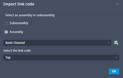
 Import Points from Link Codes. Imports points from a specified assembly or subassembly in the drawing. In the resulting Import link code dialog box, first select the option between subassembly or assembly, then select from the drop-down list, or click
 to manually choose a subassembly or assembly from the drawing. Once selected, specify a link code from the drop-down.
 Import Points from a CSV File. Imports points for a customized channel from a CSV file.
 Export Points from a CSV File. Exports points from a customized channel to a CSV file.