This section is only relevant to Water Quality Simulations.
The water quality model used in InfoWorks ICM was developed as the result of an international development project between Wallingford Software Ltd in the UK, and Anjou Recherche in France, to develop a water quality model for HydroWorks. The water quality model benefits from expertise gained during the development of MOSQITO and HydroWorks at Wallingford Software and FLUPOL at Anjou Recherche.
The model allows the simulation of the build-up of sediment in the network and the movement of sediment and determinants through the drainage system during a rainfall event.
Relationship to the Hydraulic Model
The water quality model involves a separate calculation process that effectively occurs in parallel with the hydraulic modelling calculations.
Water quality calculations may not take place on every hydraulic timestep. The calculation frequency depends on the value set for the QM Multiplier field on the QM Parameters Dialog. A QM Multiplier of 3, for example, would mean water quality calculations on every third hydraulic timestep. A QM Multiplier of zero (the default) means that calculations take place at every major timestep, and also at intermediate timesteps if the hydraulic engine divides the timestep for improved accuracy.
Water quality calculations take place after the hydraulic calculations for each timestep. Some output from the hydraulic model is fed in as input to the water quality model. There is the option to feed back varying sediment depth from the water quality model to the hydraulic model. This option is set on the QM Parameters Dialog. If this option is not selected, the hydraulic model does not know about this varying sediment depth, and continues to use the fixed Sediment Depth value set in the Conduit parameters.
The diagram below shows how the various parts of the InfoWorks ICM simulation engine interact. Hydraulic modelling aspects are at the top of the diagram. Water quality aspects are at the bottom. Shared aspects are in the middle.
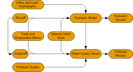
Structure of the Water Quality Model
The diagram is intentionally symmetrical. Every aspect of the hydraulic model has an equivalent area in the water quality model.
The diagram shows that the Runoff Model and the Hydraulic Model provide information for their water quality equivalents, but there is no feedback from the water quality side to the hydraulic modelling.
The table below shows how some of the components of the hydraulic model map onto components of the water quality model:
|
Hydraulic Model |
Water Quality Model |
|---|---|
|
Runoff |
Washoff and Gully Pot flushing |
|
Wastewater event |
Wastewater additional water quality parameters |
|
Trade waste event |
Trade waste additional water quality parameters |
|
Inflow and Level Events |
Pollutograph data |
|
Subcatchment Runoff Initial Conditions |
Subcatchment Sediment Initial Conditions |
|
Network hydraulic parameters |
Network water quality parameters |
|
Simulation event inputs |
Water quality event inputs |
Components of the Water Quality Model
Water Quality Determinants and sediment can enter the model from a number of sources. The diagram below shows the various components of the model.
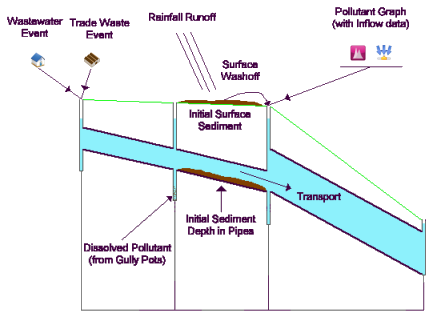
Components of the Water Quality Model
The water quality model carries out its calculations in three stages for each timestep:
- The Network Model calculates the concentration of dissolved pollutants and suspended sediment at all nodes using a Conservation of Mass equation
- The Conduit Model calculates the concentration of dissolved pollutants and suspended sediment along each conduit
- The Conduit Model then calculates the erosion and deposition of sediment in each conduit
Dry Weather
- Sediment will build up and reach a steady state on the catchment surfaces
- A layer of active sediment will build up in conduits. This active sediment can be transported by flows in the network. Active sediment sits on top of a fixed layer of bedded sediment that does not change during the simulation. See Sediment.
- Inflows of sediment and pollutant that follow a 24 hour pattern can come from areas of population (wastewater event) and industrial sources (trade event). See Trade and Wastewater Events.
- Inflows of sediment and pollutant that do not follow a 24 hour pattern, such as weekly tank flushing at an industrial plant, can be applied using a pollutant graph associated with an inflow hydrograph. See Pollutographs.
Storms
During a storm event, the dry weather inputs will continue.
- Rainfall will generate runoff from the catchment into the network. This, in turn, causes sediment to be eroded from the catchment surface and washed into the network
- Dissolved pollutants are also flushed into the system by surface runoff
- Increased flow in the network causes an increase in erosion and transport of sediment through the network.