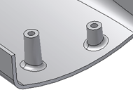
To Create a Boss Feature
Build a boss feature on a part using points of a 2D sketch or using On Point placement.
Create a Boss from 2D Sketch Points
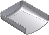
Before starting, create or import a thin-walled part that includes a 2D sketch with a couple of points corresponding to the boss placements.
Click 3D Model tab
 Plastic Part panel
 Boss
Boss  .
.In the Shape tab of the Boss dialog box, choose Placement: From Sketch and then choose a boss type:
- Head
 . It is where the head of the fastener stays.
 - Thread
 . It is where the thread of the fastener engages.
- Head
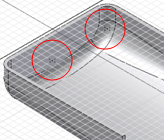
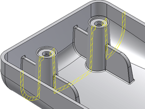
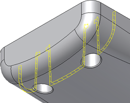
Using the Centers and Solid selectors, click in the graphics window to choose the points in the sketch and, if there’s more than one solid in the part file, the target body.
Note: If the sketch is the only one with points, they are automatically selected.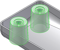
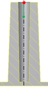
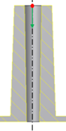
If desired, click Flip
 to reverse the direction.
The direction is automatically set as the one to the closest distance with the part bodies along the sketch plane normal axis. You can also flip the direction by dragging the direction preview arrow.
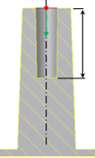
Specify the Offset From Sketch Plane and Fillet values:
- Offset From Sketch Plane. Enter a positive value to start the boss above the sketch plane. Use a negative value to start below the sketch.
- Fillet
 . The constant fillet radius at the intersection between the boss (and ribs) with the target part body.
For head-type bosses, specify parameters on the Head tab of the Boss dialog box, or use the manipulators until the appropriate dimensions are reached.
- Counterbore
 . Specify Wall Thickness, Shank Height, Clamp Height, Shank Diameter, Clamp Diameter, and Head Diameter.
 - Countersink
 . Specify Wall Thickness, Shank Height, Clamp Height, Shank Diameter, Clamp Diameter, Head Diameter, and Countersink Angle.
 - Draft Options. For both Countersink and Counterbore heads, specify the Outer Draft Angle, Inner Draft Angle, Shaft Draft Angle, and Clamp Draft Angle.
- Counterbore
For thread-type bosses, specify parameters on the Thread tab of the Boss dialog box, or use the manipulators until the appropriate dimensions are reached.
Hole. If deselected, the thread boss models an ejector pin. Specify Thread Diameter and Outer Draft Angle. If selected, choose Depth, Full Depth, or Through as the Hole type.
Depth. Specify the Thread Diameter, Thread Hole Diameter, Thread Hole Depth, Outer Draft Angle, and Inner Draft Angle.
Full Depth. The hole is automatically extended to the internal wall face. The best practice is to avoid sink marks in molded plastic parts. Specify the Thread Diameter, Thread Hole Diameter, Outer Draft Angle, and Inner Draft Angle.
Through. The hole cuts the entire part. Specify the Thread Diameter, Thread Hole Diameter, Outer Draft Angle, and Inner Draft Angle.
(Optional) In the Ribs tab, select Stiffening Ribs and enter the Number of Stiffening Ribs around each boss as well as the Rib Thickness, Rib Draft, Shoulder Length, Top Offset, Shoulder Radius, and Flare Angle.
To add rib fillets, specify Fillet Options:
- Rib Radius. The radius of the edges of the rib.
- Blend Radius. The radius at the intersection between the ribs and the boss.
- Start Angle. When placement is On Sketch, the Start Angle is the first rib inclination angle with respect to the sketch X axis. When Placement is On Point, the rib start angle is determined by a projected line on a plane that is normal to the boss direction.
- Space Angle. The angle to fill. This value is divided by the number of stiffening ribs to determine the angle between ribs.
Click OK.
Create a Boss from a 3D Point
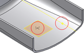
Before starting, create or import a thin-walled part. Place a Boss feature on the circular edge at a position that is not convenient for the On Sketch placement style. For example, choose a point on the edge where the hook direction is not likely to be aligned with a sketch X or Y axis. Build the construction elements. Create one sketch point and one 3D work feature where the bosses are needed.
| |  |
Click 3D Model tab
Plastic Part panel Boss .In the Shape tab of the Boss dialog box, choose Placement: On Point and then choose the Head
or Thread boss type.Using the Centers and Solid selectors, click in the graphics window to choose the sketch points and, if there’s more than one solid in the part file, the target body.
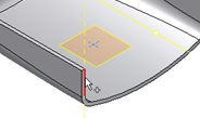
Specify the Direction and Fillet values:
- Direction
 . Use the selector to define the boss direction. The Direction is the same for all the bosses in the same feature.
 - Fillet . The constant fillet radius at the intersection between the boss (and ribs) with the target part body.
- Direction
Adjust the Head and Ribs or Thread and Ribs parameters as desired and click OK.