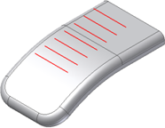
About the Grill Feature
The Grill feature is used to create vents or openings on the thin walls of a part to provide air flow for internal components.
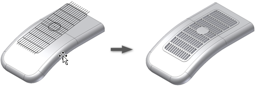
Elements of a Grill
A grill is created by projecting the patterns of one or more 2D sketches on the surface of the part, and defining the four aspects of the grill in the Grill dialog box:
Boundary. Specifies the closed extent of the grill. The selection of the Boundary profile implicitly determines the grill direction as the direction from the profile centroid to the closest point of the part along the profile plane normal. The boundary profile is required to build the grill.
Island. An area filled with material, usually at the center of the grill. The island often has the same thickness as the shell. It must be a closed sketch.
Ribs. One set of curves that fills the grill area. The external faces of the ribs are flush or slightly recessed with respect to the boundary external face. Ribs can extend below the internal face of the target body.
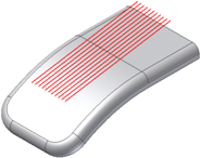
Spars. A secondary set of curves, usually added to improve the stiffness of the ribs.
Draft. The grill requires a draft angle and, optionally, an offset from the boundary outside of the parting surface.
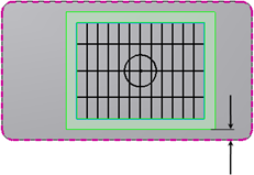
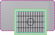
External Contour and Tolerance
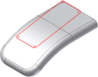
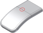
In a grill, the boundary external contour projection (plus a 10-percent tolerance band around the external contour) must remain entirely within the part surface. No material gaps (holes) are allowed inside the boundary projection. Examples are shown in the following images:
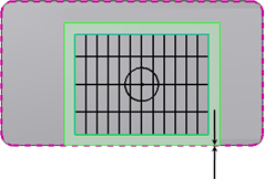
The boundary sketch is the only mandatory element when building a grill. The area of the openings of a Grill feature is reported in the Flow area section of the dialog box and in a Reference parameter. The flow area does not consider the optional draft angles.
About Draft
The draft angle for the grill requires only two parameters:
- A draft angle (no sign).
- (Optionally) the offset from the Boundary Outside of the parting surface.
If you input the draft angle, the software chooses the “best practices” draft configuration. If you define the parting element (as the offset from the Boundary external face of the parting surface), then the draft is modeled accordingly without any verification of the manufacturability.
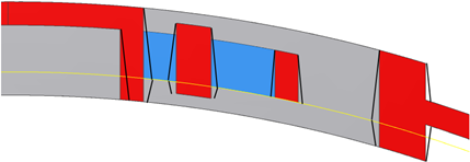
The “best practice” draft is defined as the following:
- The parting is as far as possible from the “Outside” defined by the position of the Boundary profile (to minimize the aesthetic damage of the parting lines).
- Minimization of the double draft (to simplify manufacturing).
- The neutral always coincides with the “Outside” face of each element (to have the nominal dimensions on the visible part of the Grill).
In practical terms, the parting element contains the inside faces of either the Boundary or the Spar.
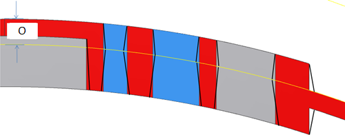
Alternatively, define the parting element as the part surface (before the application of the Grill) at a given Offset O from the Boundary outside face. By changing the offset amount, you can position the parting element where deemed necessary. The outside faces remain neutral.