Assembly Enhancements
Check out the assembly enhancements for this release, including various constraint and model state enhancements.
Model State Enhancements
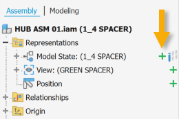
You can now use a quick-create + button on representation browser folders to create a new representation without opening the context menu. Hover a folder to display the button, then click + to create:
- Model States: A new model state. The button is disabled with a tooltip when a substitute is active.
- iComponent or iAssembly table: A new iPart or iAssembly member.
- Design Views: A new view representation.
- Positional Representations: A new positional representation.
For more information see Configurations and Representations.
Simplified Model State Context Menu
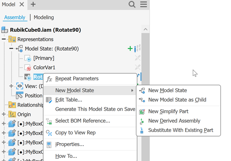
The model state context menu is now context-sensitive, showing only the commands that apply to your current selection.
When the active model state or the Model States folder is selected:
- New Model State: Creates a new top-level model state and activates it automatically.
- New Model State as Child: Creates a new child of the active model state and activates it automatically.
When a different (inactive) model state is selected:
- Duplicate Model State: Creates a top-level copy. The duplicate is not activated.
- Duplicate Model State as Child: Creates a copy nested under the same parent as the source. If a child model state is selected and its parent differs from the duplicate source, the parent name` is added to the command name. The duplicate is not activated.
For more information see To Create Model States and To Edit Model States.
Drag to Reorganize Model States
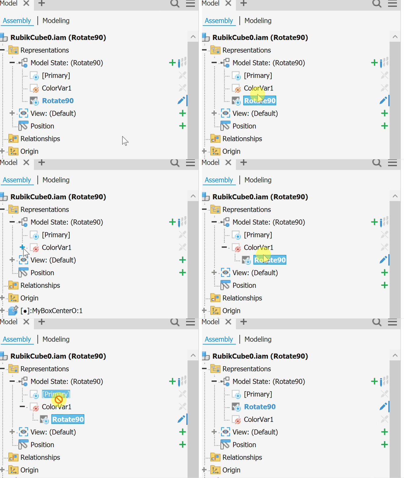
You can now drag model states in the browser to create or remove parent-child (delegation) relationships and reorder your model state hierarchy.
- Delegate: Drag a top-level model state onto another top-level model state to make it a child. A top-level model state that already has non-substitute children cannot become a child.
- Undelegate: Drag a child model state out of its parent to promote it to the top level.
- Switch parent: Drag a child model state onto a different top-level model state to reparent it.
- Reorder: Drag to reorder model states at the top level, or reorder children within the same parent.
- Multi-select: Hold Ctrl or Shift to select multiple model states, then drag them together.
Substitutes cannot be reparented by drag-and-drop. Edit in place is not supported.
For more information see To Create Model States, and To Edit Model States.
Improved Visibility of Model State Delegation
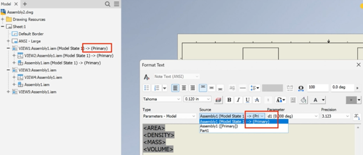
When a model state delegates to another, the delegation relationship is now indicated using arrow notation (→), helping you understand why physical properties or parts lists may differ from expectations.
The notation appears in:
- Format Text dialog
- Create Parts List dialog
- Place Drawing View dialog
- Drawing view and IPN scene names in the browser
- Derive Assembly dialog and browser node
The notation format depends on context. When a component name precedes the model state name, model state names are parenthesized (Primary uses square brackets):
Assembly Name.iam (Model State 1) → [Primary]Assembly Name.iam (Model State 1) → (Model State 3)
In a combobox listing only model states, names are not parenthesized:
Model State 1 → [Primary]Model State 1 → Model State 3
For more information see About Model States.
Model State Elaboration Status Icons
The model state browser node now displays an icon that indicates whether a model state's generated files are current. When a model state is out of date or has not been generated, the icon alerts you before you place the model state in another file.
Three icon states are shown:
- Out of date: The model state has an existing elaboration, but it has gone stale and needs to be regenerated.
- No elaboration: No generated files exist for the model state.
- Pending: The model state is set to generate on the next save.
Tooltips on model state browser nodes also display these icons along with the model state name.
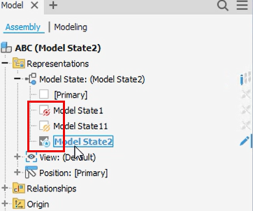
For more information see About Model States.
Model State iProperty Values in Drawing Parts Lists
Custom iProperty values driven by exported parameters that are captured by a model state now display correctly in drawing parts lists. Previously, an incorrect value could be shown.
Constraint Enhancements
Separate Ribbon Entry for Each Constraint Type
You can now place assembly constraints directly from the ribbon. On the Assemble tab Relationships panel, the Constraint commands include separate entries for all available constraint types. Selecting a command opens the Place Constraint dialog box with that constraint type active.
The Constrain command remains available when you want to choose the constraint type in the dialog box.
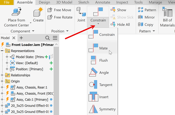
For more information see Place Constraint Reference - Assembly Tab.

Multi-Select for Tangent Constraints
Apply a Tangent constraint to multiple components at once using the new multi-select mode in the Constraint dialog.
The second selector in the Tangent Constraint dialog now supports multi-select. Select a base component, then constrain as many additional components as needed in a single operation. A separate Tangent constraint is created for each component in the second selection.
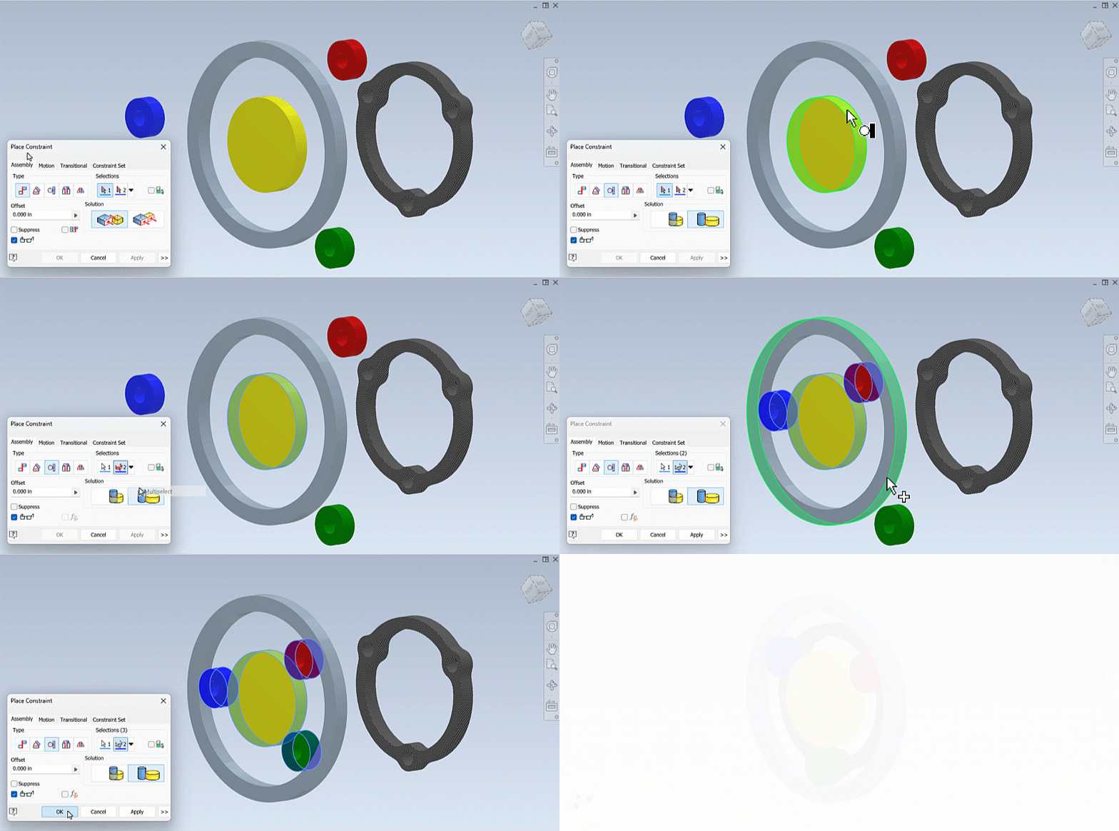
Apply Tangent constraints to multiple components
- On the ribbon, click Assemble tab
 Relationships panel Constraint Tangent.
- For Selection 1, select the base component. The component is temporarily grounded while the constraint is applied.
- In the Selection 2 flyout, choose Multiselect.
- Select the components to constrain.
- Click OK to apply the constraints and close the dialog, or Apply to apply and continue adding constraints.
Key behaviors
- Separate constraints: A distinct Tangent constraint is created for each component in Selection 2.
- Deselect: Hold Ctrl or Shift and click an already-selected component to remove it from Selection 2.
- Consistent settings: Suppress, offset, solution, and limits settings apply to all constraints created in the operation.
- Persistent mode: The selected flyout mode (Single Selection or Multiselect) is retained between Inventor sessions.
- Edit: When editing an existing Tangent constraint, the flyout is disabled and only single selection is available.
For more information see Place Tangent constraints in assemblies.
Temporarily show Origin geometry while adding constraints
While using the Constraint command, you can temporarily display the Origin geometry of the selected component, including origin planes, axes, and the origin point.
Hover over the desired component, then press and hold the Alt key to display its Origin geometry. When you hover over an empty area, the Origin geometry of the top-level assembly is displayed.
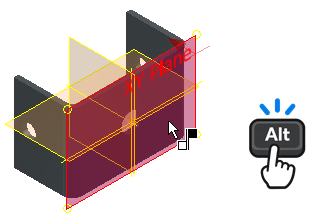
For more information see Assembly Constraints.
Place and Insert Enhancements
You can now place multiple constrained components from the source selector in one operation. On the Place and Insert property panel, in Input Geometry, turn on Place constrained components at the end of the source selector to place multiple instances constrained to the selected source (for example, a bolt and washer together).
The toggle is off by default and retains the last setting between sessions.
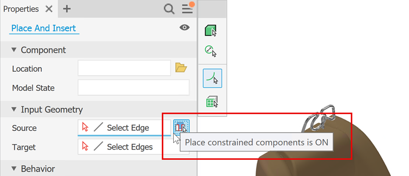
For more information see To Place and Insert Parts.
Mirror Components Enhancements
The redesigned Mirror Components dialog groups Mirror and Reuse options. At the top of the dialog, you'll find Components, Mirror Plane, and Create Mirror Pattern controls.
Use the new Create Mirror Pattern check box — which replaces the separate mirror pattern and flat structure controls — to choose your output: select it to create a mirror pattern, or clear it to create a legacy mirror. Status icons show you the state of each component selection, and buttons appear or are hidden based on the operations you select.
Model browser icons for component mirror, source, and target nodes are also updated.
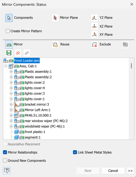
For more information see To Mirror Assembly Components and Mirror Components: Reference.
Centered preview when you start Place
You can now see a preview of the component centered in the graphics window as soon as you select a file in the Place Component dialog box — even before your cursor enters the canvas. The preview is not attached to the cursor until you move the mouse over the graphics window, at which point it transitions smoothly to follow the cursor.
This behavior applies to all Place entry points, including manual placement, Autodesk Assistant, MCP tools, Place from Vault, and Place from Content Center. Non-interactive placement at a supplied transform or origin is unaffected.
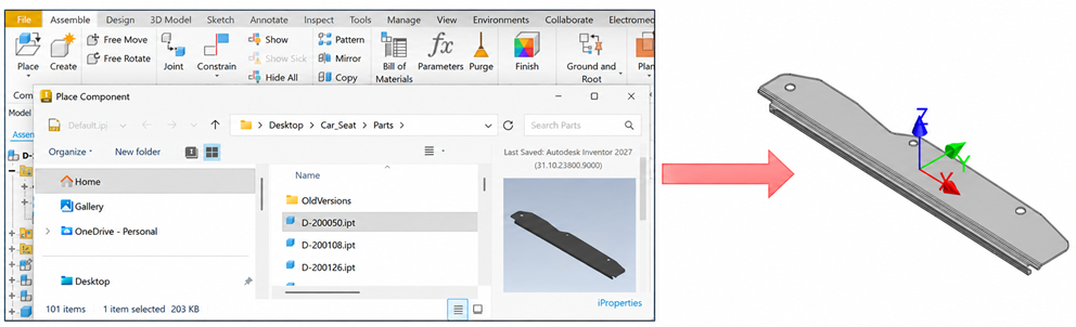
For more information see To Place Components in Assemblies.