The parameters of the seismic simplified analysis according to the equivalent lateral force method depend on a seismic code and a method of defining values of the fundamental periods selected in the Seismic Analysis dialog.
Access
- Click
Tools
 Job Preferences Design Codes.
- Go to the Loads section, and then select RPA 2024 from the seismic loads menu.
- Click
Analysis
Analysis Types. The Analysis Types dialog displays.
- Click New. The New Case Definition dialog opens.
- Select Seismic (Equivalent Lateral Force Method), and click OK. The Seismic Analysis dialog opens.
- Click Seismic Analysis Parameters. The Parameters dialog opens.
Dialog elements
Fundamental period (T0)
The parameters of the seismic simplified analysis according to the equivalent lateral force method depend on a seismic code and a method of defining the value of the fundamental period selected in the Seismic Analysis dialog.
- Approximate (according to the seismic code)
- User-defined value in seconds
- Precise (using oscillation period based on modal analysis)
Approximate method
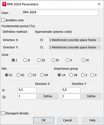
The approximate fundamental natural period T0 is calculated according to the RPA 2024, clause 4.2.4. using the empirical formula (4.4) depending on the case is as follows:
T0 = Tempiric = CT * h 0.75 [s]
where:
- h - structure height (m), defined automatically by difference between Structure range and Reference level
- CT - coefficient depending on the selected structure type, Table 4.3:
- 0,075 - Reinforced concrete space framework without masonry infill
- 0,085 - Steel frames without masonry infill
- 0,050 - Steel or Reinforced concrete space framework with masonry infill
- 0,050 - Other types of structures
User defined
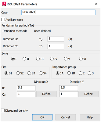
The fundamental period T0 values are entered manually by the user in each X and Y direction.
According to clause 4.2.4 point 4 the value of fundamental period T0 to be used in the equivalent static method must not exceed by more than 30% those estimated from the empirical formula: Tmax = 1.3Tempiric
Precise method
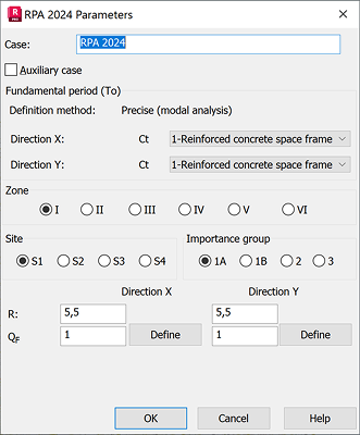
In this method a modal analysis case is created. Fundamental period is calculated for both X and Y directions.
If the option "Periods with maximal mass participation" is off in the Seismic Analysis dialog, then the first mode is taken as fundamental period.
If this option is on, period T is taken from the mode, which fulfills limitations and gives the maximum participating masses in the direction.
According to clause 4.2.4 point 4 the value of fundamental period T0 to be used in the equivalent static method is automatically limited: if T < 1.3Tempiric then T0 = T if T ≥ 1.3Tempiric then T0 = 1.3Tempiric
Code parameters
To complete the seismic analysis according to the rules given in a code, define the following parameters:
- Zone - The Seismic zone number given in the code, clause 3.1, the value is assigned according to the choice of seismic zone. For determining design seismic force, the country is classified into seven seismic zones (0 to VI) as shown in Figure 3.1 The selection of the zone determines the value of acceleration parameter A, according to Table 3.2.
- Site - For determining the correct spectrum to be used, the type of soil on which the structure is placed shall be identified by the classification given in clause 3.2, as Soil type S1, S2, S3, S4. The selection of the site determines the value of site parameter S, and characteristic period for spectrum definition T1, T2, T3, according to Table 3.3 and 3.4.
- Importance group - Classification of the structure importance group is given in clause 3.4, and the importance factor value is assumed according to Table 3.10,
- Behavior factor - Specify the value of the Behavior factor in each X and Y direction, according to point 3.6. Determine the value according to Table 3.17 depending on the structure type.
The Behavior factor is a reduction factor of the design response spectrum in relation to the elastic response spectrum. You can edit its value after selecting the Design spectrum option.
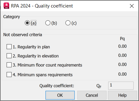
Quality coefficient
Quality factor is determined in each X and Y direction, according to the Equation (3.23) QF = 1 + Σ Pq depending on criteria classified with Table 3.18. Click Define button to choose Category and not observed criteria, quality factor is calculated accordingly.
Calculation of the Total Seismic Force
The total seismic force, V, applied to the base of the structure, is calculated successively in two orthogonal horizontal directions, according to Equation (4.1):
V = λ * Sad/g (T0) * W
where:
- Sad/g (T0) is the value of seismic acceleration coefficient according calculation spectrum given in clause 3.3.3. for the estimated fundamental period T0,
- λ correction coefficients, applied automatically as 0,85 if T0 ≤ (2*T2) and if the building has more than 2 levels, otherwise λ =1,0
- and W is the effective seismic weight of the structure as per Equation 4.3. The effective seismic weight of each story is calculated based on the self-weight of the structural elements, as well as added masses and loads converted to masses. If you want to consider live loads in seismic weight, you need to convert live load cases to masses with required accompanying coefficient.
The total design lateral seismic force V is distributed over the height of the structure with the Equations (4.7) & (4.8):
V = Ft + Σ j n F i
The concentrated force Ft, at the top of the structure, allows for the influence of higher vibration modes to be taken into account. It must be determined using the formula: (Ft = 0.07*T0*V), where (T0) is the fundamental period of the structure in seconds. The value of Ft will never exceed 0.25*V and will be taken as 0 for T0 ≤ 0.7s.
The remaining part of V, i.e. (V −Ft ), is distributed to each level Fi
F i = (V - Ft) * W i *h i / ( Σ j n W j * h j )
where
- Wi, Wj - Portion of the total effective seismic weight of the structure (W) located or assigned to level i or j respectively
- hi - height from base level to appropriate floor level i
- n - number of stories in the building, it is the number of levels at which masses are located
Disregard density
Excludes the density of the structure element (ρ=0) during the estimation of effective seismic weight applied to the stories of the structural model during analysis.
In this case you need to apply added masses or loads conversion to masses as defined in Load Types dialog at Load to Mass Conversion tab.
The details concerning this structure analysis method can be found in the mentioned code of standard RPA 2024 D.T.R. - B.C.2.48.
You can examine all the input parameters and spectrum values in the Calculation Notes (open Analysis Calculation Notes Simplified/Full Note).