Review and modify the values of section shape dimension parameters of concrete structural framing elements.
These type properties are created from the Section Shape family category parameter of the element.
| Section shape | Available shape dimension parameters |
|---|---|
Rectangle
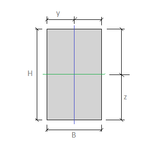 |
B. Width: the external width of the section shape. H. Height: the external height of the section shape. y. Centroid Horizontal: the distance from the centroid of the section shape to the left extremities along the horizontal axis. z. Centroid Vertical: the distance from the centroid of the section shape to the lower extremities along the vertical axis. |
L-Shape
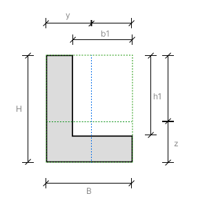 |
B. Width: the external width of the section shape. H. Height: the external height of the section shape. h1. Cut Height: the height of the cut in an L-shape. b1. Cut Width: the width of the cut in an L-shape. y. Centroid Horizontal: the distance from the centroid of the section shape to the left extremities along the horizontal axis. z. Centroid Vertical: the distance from the centroid of the section shape to the lower extremities along the vertical axis. |
Round
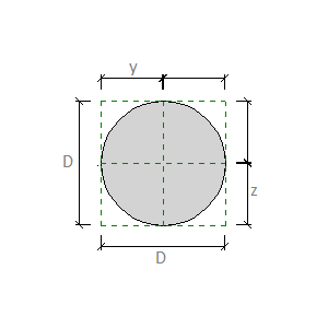 |
D. Diameter: the external diameter of the round section shape. y. Centroid Horizontal: the distance from the centroid of the section shape to the left extremities along the horizontal axis. z. Centroid Vertical: the distance from the centroid of the section shape to the lower extremities along the vertical axis. |
T-shape
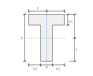 |
B. Width: the external width of the section shape. H. Height: the external height of the section shape. h1. Cantilever Height: the height of the cantilever flange in the section shape. b1. Cantilever Length: the length of the cantilever flange in the section shape. y. Centroid Horizontal: the distance from the centroid of the section shape to the left extremities along the horizontal axis. z. Centroid Vertical: the distance from the centroid of the section shape to the lower extremities along the vertical axis. |
I-shape
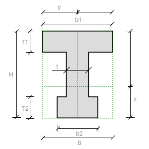 |
B. Width: the external width of the section shape. H. Height: the external height of the section shape. T1. Top Flange Thickness: the distance between the exterior surfaces of the top flange in the section shape of a castellated or welded element. b1. Top Flange Width: the external width of the top flange in the section shape of a castellated or welded element. T2. Bottom Flange Thickness: the distance between the exterior surfaces of the bottom flange in the section shape of a castellated or welded element. b2. Bottom Flange Width: the external width of the bottom flange in the section shape of a castellated or welded element. t. Web Thickness: the distance between the exterior surfaces of the web in the section shape. y. Centroid Horizontal: the distance from the centroid of the section shape to the left extremities along the horizontal axis. z. Centroid Vertical: the distance from the centroid of the section shape to the lower extremities along the vertical axis. |
Select the Enable Auto-Calculation of Values checkbox in the Type Properties dialog to automatically calculate the following common parameters for all these shapes:
- Section Area
- Perimeter
- Moment of Inertia Strong Axis
- Moment of Inertia Week Axis
- Elastic Modulus Strong Axis
- Elastic Modulus Week Axis
- Plastic Modulus Strong Axis
- Plastic Modulus Week Axis
- Torsional Moment of Inertia
- Torsional Modulus
- Warping Constant
- Shear Area Strong Axis
- Shear Area Week Axis
- Principal Axes Angle