Most links in a WS Pro model are non-channel links: pipes, pumps, valves and similar components, which are always pressurised - the water completely fills them, the flow is driven by the difference in piezometric head between their ends, and they are solved by the WS Pro pressurised solver.
A channel is a link where that assumption does not hold. Flow is driven by gravity down the bed slope, the water surface is free to rise and fall within the section, and the depth of flow is itself one of the unknowns.
The term channel describes the flow regime, not the shape of the section:
- A channel may be given an open section (rectangular, trapezoidal, U-shaped, etc.) or a closed one (circular, egg-shaped, arched, etc.). A closed section running part-full is still a channel.
- A channel is allowed to pressurise. When the flow surcharges and fills the section, the solver continues to solve the same link without any change of model or any intervention from you (see section Surcharge and pressurisation).
Because of the second point, a channel is not the same thing as a "non-pressurised" link. It is a link whose normal state is free-surface flow, and which handles pressurisation when it occurs.
Parts of a channel
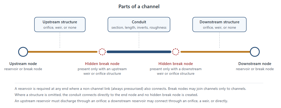
A channel is a single link in your network, but hydraulically it is a short chain of components. The chain always contains a conduit — the length of channel section itself — and it may additionally carry a hydraulic structure at either end that controls how water enters and leaves.
| Part | Required | Description |
|---|---|---|
| Upstream node | Yes |
A reservoir or a break node. See section Connecting channels to the rest of the network. |
| Upstream structure | No |
An orifice, a weir, or nothing at all. Controls the inflow. |
| Conduit | Yes |
The channel itself: cross-section shape, width, height, length, upstream and downstream invert levels, and roughness. |
| Downstream structure | No |
An orifice, a weir, or nothing at all. Controls the outflow. |
| Downstream node | Yes |
A reservoir or a break node. |
A break node is not a separate object that you create. Where a regular WS node sits at the end of a channel and connects only to channels, the solver treats it as a break node: a junction that passes flow and water level between the channels meeting there, with no storage of its own.
Each end of a channel carries at most one
Where a structure is present, the solver inserts a short internal junction - a hidden break node- between the structure and the conduit, so that the structure and the conduit each have a node at both of their ends. These hidden nodes are created and managed by the solver. They are not part of your network, they carry no demand or storage, and their invert levels are taken from the conduit. Where a structure is omitted, no hidden node is created and the conduit connects straight to the end node.
The solver checks the invert levels along the whole chain before the run starts and reports any inconsistency - for example an orifice invert below the conduit invert, a weir wider than the section it discharges from, or a break node whose ground level does not match the conduit invert it connects to.
Connecting channels to the rest of the network
Two node types may sit at the end of a channel, and the choice is governed by what else connects there.
Reservoirs are the interface between the non-channel (pressurised) and the channel parts of the network. Wherever a non-channel link and a channel meet, a reservoir must sit between them. The reservoir provides the storage volume and the free water level that let the two solvers exchange water without either having to make assumptions about the other.
Break nodes join channels to channels. A break node may carry nothing but channels: connecting a non-channel link to one is not allowed and stops the run.
In summary:
| Connection | Allowed |
|---|---|
| Channel - reservoir - channel | Yes |
| Channel - reservoir - non-channel link | Yes |
| Channel - break node - channel | Yes |
| Channel - break node - non-channel link | No |
| Channel - any other node type | No |
Two further rules apply where a reservoir is used:
- An upstream reservoir must discharge into the channel through an orifice. A direct connection, or a connection through a weir, is not supported.
- A downstream reservoir may be reached through an orifice, through a weir, or directly. Where the connection is direct, the conduit invert must sit at or above the top water level of the reservoir, so that the channel always discharges freely into it.
Cross-section and roughness
Cross-section: A channel takes either a built-in section shape or a user-defined one, sized by a width and a height. The width and height are validated against the rules for the chosen shape before the run starts.
The built-in closed shapes are:
| Shape | Description |
|---|---|
| CIRC | Circular |
| RECT | Rectangular |
| UTOP | U-shaped |
| OVAL | Oval |
| EGG | Egg-shaped, touching circles |
| EGG2 | Egg-shaped, non-touching circles |
| CNET | Cunette |
| ARCH | Arch |
| ARCHSPRUNG | Sprung arch, which takes a springing height in addition to the width and height |
The built-in open shapes are:
| Shape | Description |
|---|---|
| OREC | Open rectangular |
| OU | Open U-shaped |
| OEGB | Open egg-shaped, broad |
| OEGN | Open egg-shaped, narrow |
| OT4:1, OT2:1, OT1:1, OT1:2, OT1:4, OT1:6 | Open trapezoidal, with the side slope given by the ratio |
A user-defined shape is described by a table of left-hand and right-hand widths at a series of heights. Because the two sides are given independently, both symmetric and asymmetric sections are supported, open or closed.
Roughness: A single roughness value applies to the whole channel, expressed either as a Manning's n or as a Colebrook-White roughness height ks.
Computational points: The conduit is subdivided along its length into computational points, at a spacing chosen by the InfoWorks ICM solver from the size of the section.
How channels are solved
Channels are solved by the InfoWorks ICM solver, embedded in WS Pro. At the start of a run WS Pro builds an equivalent InfoWorks ICM network from your channels - one conduit per channel, an orifice or weir link for each structure you defined, and a node for each end node and hidden break node - and hands that network to the ICM solver. The non-channel part of the network is not passed across; it stays with the WS Pro pressurised solver.
Within each conduit the solver advances the one-dimensional Saint-Venant equations, a pair of conservation statements for mass and momentum:
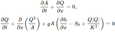
Equations (1) and (2)
where:
| Symbol | Meaning | Unit |
|---|---|---|
| x | distance along the channel | m |
| t | time | s |
| Q | discharge | m³ s⁻¹ |
| A | wetted cross-sectional area | m² |
| h | depth of flow | m |
| So | bed slope | - |
| K | conveyance, from the section geometry and the roughness | m³ s⁻¹ |
| g | acceleration due to gravity | m s⁻² |
The equations are discretised in the plane defined by distance along the channel and time, using a four-point implicit (Preissmann) box scheme weighted towards the new time level. This produces a set of non-linear algebraic equations in depth and flow at every computational point, closed by the conditions at the ends of each conduit: the water level in the node at that end, and the discharge relationship of any inlet or outlet structure (see section Inlet and outlet structures).
That set of equations is solved simultaneously across the whole channel network by Newton-Raphson iteration. Because the equations are non-linear, convergence is not guaranteed at any given time step, so the solver adapts:
- It starts from the full hydraulic time step and carries the last successful step length forward.
- If the iteration fails to converge, the step is halved and retried, repeatedly if necessary.
- If it converges rapidly, the step is doubled again, up to the full hydraulic time step.
- If halving reaches the solver's lower limit without convergence, the run reports a failure.
This sub-stepping is internal. The channels are always brought back into step with the rest of the network at the end of each hydraulic time step.
Surcharge and pressurisation
A channel that surcharges is still solved by equations (1) and (2), which assume a free surface. To keep that assumption valid when the section fills, the solver applies the Preissmann slot method to closed sections: a narrow, notional slot is added above the soffit, so that a section which is physically full still presents a small free water surface. Water rising into the slot represents the rise in pressure head above the soffit, and the flow becomes pressurised without any switch of equations or loss of mass.
The slot width is chosen automatically so that the wave celerity within the slot is roughly ten times the free-surface wave celerity of the section it sits above, subject to a minimum width of 1 mm. Making the slot narrow keeps the added storage negligible; keeping it above the minimum keeps the solution well conditioned.
Open sections need no slot: they simply keep filling until the water reaches the top of the section.
Spill
A channel with an open section has no roof, so nothing physically stops the water level rising above the top of the defined section. Where that happens, the volume held above the top of the section is treated as having left the network and is reported as a volume loss for that channel.
Closed sections do not spill. They surcharge into the Preissmann slot instead (see section Surcharge and pressurisation).
Coupling with the pressurised network
The non-channel (pressurised) network and the channel network are solved by different solvers, and they exchange information once per hydraulic time step at the reservoirs that join them.
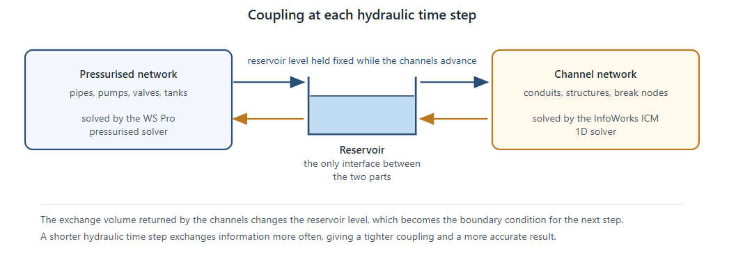
Within one hydraulic time step:
- The WS Pro solver solves the pressurised network, giving the water level at every reservoir. Channel links take no part in this solution.
- Those reservoir levels are passed to the channel solver as fixed boundary conditions, and the channel network is advanced by one hydraulic time step (internally sub-stepped as described in section How channels are solved). The reservoir levels are held constant over that period.
- The volume that has moved into or out of each reservoir through its channels is returned, together with the flows, depths and velocities in the channels themselves. The reservoir volumes are updated from that exchange combined with the demand, leakage and pressurised inflow at the same node.
- The updated reservoir levels form the boundary condition for the next step.
The strength of this coupling is set by the hydraulic time step. A long time step lets the reservoir level drift a long way before the two sides see each other again; a short one exchanges information more often and gives a more accurate result. If channel results look sensitive to the time step, shorten it.
Note that dynamic time stepping in WS Pro is driven by the pressurised network. It does not shorten the time step in response to conditions in the channels.
Inlet and outlet structures
Where you define an orifice or a weir at the end of a channel, its discharge is calculated from the water depths on either side of it:
| Symbol | Meaning | Unit |
|---|---|---|
| Du | upstream depth, measured from the orifice invert or the weir crest | m |
| Dd | downstream depth, measured from the same level | m |
| Dcl | upstream depth above the centreline of an orifice opening | m |
Both directions of flow are handled: when the downstream level is the higher of the two, the roles of Du and Dd are exchanged and the resulting discharge is reversed.
Orifice
An orifice has an invert level, a diameter Do and a discharge coefficient Cd. Its area is A0=πDo2/4, and its effective width when it runs part-full is B=A0/Do. Which equation applies depends on whether the upstream water surface has reached the soffit of the opening.
Orifice flow with free discharge, when the upstream level is above the opening and the downstream side is not submerged. The driving head is measured to the centreline of the opening:

Orifice flow, drowned, when the downstream side is submerged. The driving head is the difference across the opening:

Weir flow, when the upstream level is still below the soffit, so the opening runs part-full:

Where both regimes are admissible the solver takes the lower of the two discharges, which keeps the transition between them continuous. Submergence of weir flow is handled by a drowning correction that reduces the discharge as the downstream level approaches the upstream one, falling to zero when the two are level.
Weir
A weir at a channel end is modelled as a round-nose horizontal broad-crested weir to BS 3680 / ISO 4374 Part 4F. It has a crest level, a width B and a length L in the direction of flow. Under modular (free) flow the discharge is:

where Cd is the discharge coefficient, which accounts for the boundary layer developing along the crest,

and Cv is the coefficient of approach velocity, obtained by solving
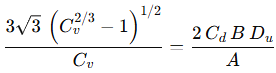
in which A is the cross-sectional area of flow in the approach channel. Neither coefficient is entered by you; both follow from the geometry and the head.
The equation for Q applies while the weir is modular. Once the downstream head exceeds about two thirds of the upstream head the weir drowns, and the discharge is progressively reduced towards zero as the two levels converge.
Currently unsupported functionality
The following are not yet supported in a model that contains channels. Each is either reported as an error that stops the run, or ignored with a warning in the run log.
| Feature | Behaviour |
|---|---|
| Water quality | Run stops |
| State files, whether saving or restarting | Run stops |
| Demand, leakage or hydrant flow at a break node | Ignored |
| Closing or isolating a break node | Ignored |
| Closing or isolating a channel link, including during fire flow analysis, critical link analysis and shutdown planning | Ignored |
| Break nodes and channel links in leak locator lists | Ignored |
| Dynamic time stepping | Runs, but the step is not restricted by channel conditions |
| Fire flow velocity constraints on channel links | Evaluated from the nominal section area, so may be inaccurate |