You can use Split Face on any non-family instance. The Split Face tool splits the selected face of the element; it does not change the structure of the element. After splitting the face, you can use the Paint tool to apply a different material to this section of face. See Applying a Material to the Face of an Element.
In the conceptual massing environment, a surface can host subregions that have their own properties. Creating subregions can help you refine your design and improve the accuracy of an energy analysis. You can assign a material to a subregion or extrude its profile into a solid or void form to change the topography of the surface.
To split a face
- Click Modify tab
 Geometry panel
 (Split Face). Note: In the conceptual design environment on the Options bar, you can select a Projection Type for the UV grid. Select Top down, Parallel to level, or Follow surface UV from the drop-down. The Projection Type will align the subregion UV grid as specified.
Projection type examples
- Top Down
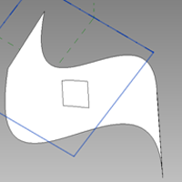
Top down is useful for drawing skylights.
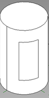
- Parallel to level
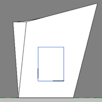
Parallel to level is useful for drawing windows.
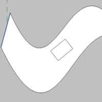
- Follow surface UV

- Top Down
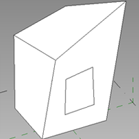
- Place the cursor on the element face to highlight it. You may need to press Tab to select the desired face.
- Click to select the face.
- Sketch the face area to split. Note: The sketch must be in a closed loop inside the face or an open loop that ends on the boundary of the face.
- Click
 (Finish Edit Mode).