You can cut an elevation, section, or callout view at the far clip plane. You activate this feature using the Far Clipping parameter for the view. The far clip plane is defined with the Far Clip Offset parameter.
Example
The following image shows the clip plane for the model and the resulting elevation view representations for the Far Clipping parameter options (Clip without line, Clip with line, and No clip).
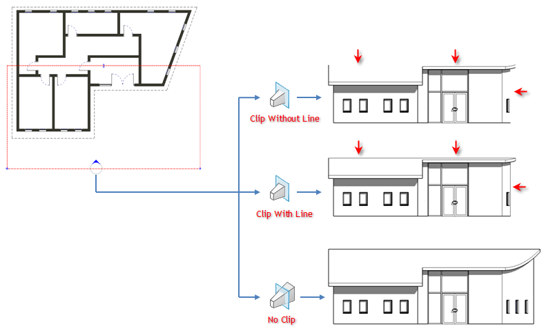
Elements that have symbolic representation in certain views (such as structural beams) and non-cuttable families are not affected when you cut an elevation, section, or callout view by the far clip plane. They will display and are not cut.
This property does affect printing.
To cut by the far clip plane
- In the Project Browser, right-click the view you want to cut by the far clip plane, and click Properties.
Alternatively, if the view is active in the drawing area, right-click and click View Properties.
- On the Properties palette, locate the Far Clipping parameter.
The Far Clipping parameter is available for elevation, section, and callout views. To use this parameter in a callout view, for the Far Clip Settings parameter, specify Independent.
- Click the button in the value column.
The Far Clipping dialog displays.
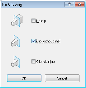
- In the Far Clipping dialog, select an option, and click OK.
- Enter a value for Far Clip Offset to specify where the view will be clipped when the Far Clipping property is active.