Universal Abutment Parameters
The following parameter values are applicable to all abutment parts. Dimension sets determine the location and positioning of the abutment.
Longitudinal Placement
The following universal parameters position an abutment along a road alignment.
| Parameter Description | Content Parameter | Parametric Value | InfraWorks Set/Read | Inventor | Revit |
|---|---|---|---|---|---|
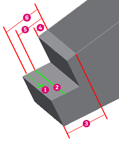
| Origin to back of ballast wall | OriginToBBW | The distance from back of the ballast wall to the part origin. Positive is in front of the back of the ballast wall; negative is behind. | Yes/No | No | Yes |
| Ballast wall height | BallastWallHeight | The distance from the bottom to the top of a ballast wall. | Yes/Yes | No | No |
| Ballast wall thickness | BallastWallThickness | The distance from the back to the front of a ballast wall. | Yes/No | No | Yes |
| * Centerline of bearing to back of ballast wall | CLBearingToBBW | The distance from the back of the ballast wall to the bearing line. | Yes/No | No | Yes |
| * Seat width | SeatWidth | The distance from the back of the ballast wall to the front of seat. | Yes/No | No | Yes |

 Abutment Origin Abutment Origin |
 BallastWallThickness BallastWallThickness |
 Bearing Line Bearing Line |
 CLBearingToBBW CLBearingToBBW |
 SeatWidth SeatWidth |
 OriginToBBW OriginToBBW |
Longitudinal Slope
Both longitudinal slopes are currently set by InfraWorks, to the grade of the alignment over the abutment. These are not configurable.
| Parameter Description | Content Parameter | Parametric Value | InfraWorks Set/Read | Inventor | Revit |
|---|---|---|---|---|---|
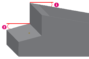
| Longitudinal slope | LongitudinalSlope | The angle of a ballast wall top elevation. This is positive when increasing in the forward direction of the abutment. | No/Yes | No | No |
| Seat longitudinal slope | SeatLongiSlope | The angle of a seat top elevation. This is positive when decreasing in the forward direction of the seat. | No/Yes | No | Yes |

 LongitudinalSlope LongitudinalSlope |
 SeatLongSlope SeatLongSlope |
In the diagram, the forward direction is right to left. SeatLongiSlope is positive when the seat top elevation decreases in the forward direction.
Vertical Placement
Vertical placement parameters vertically aligns the abutment and allows for manual refinement through offsets.
| Parameter Description | Content Parameter | Parametric Value | InfraWorks Set/Read | Inventor | Revit |
|---|---|---|---|---|---|
| Match by surface to bearings | MatchBySurfaceToBearings | The method for vertically aligning the abutment under deck, girders and bearings. Either True or False (see below for more information). | Yes/No | No | Yes |
| Ballast wall top vertical offset | BallastWallTopVerticalOffset | Adjusts the ballast wall up (positive) or down (negative) by this distance. | Yes/No | No | Yes |
| Vertical offset from seat top | SeatTopVerticalOffset | Adjusts the seat up (positive) or down (negative) by this distance. | Yes/Yes | No | Yes |
When MatchBySurfaceToBearings is set to True, the abutment aligns with the ballast wall meshes touching the bottom of the deck and the seat meshes touching the bottoms of the bearings. This is the more precise method.
When MatchBySurfaceToBearings is set to False, 2 planes are determined: one to the left of the origin and one to the right. The ballast wall planes align to touch the deck bottom. The seat planes align to touch bearing bottoms. This method is faster but less precise.
Lateral Widths
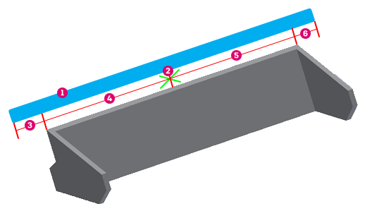
InfraWorks calculates LeftWidth and RightWidth based on the left and right widths of its deck at the abutment, and overhangs.
| Parameter Description | Content Parameter | Parametric Value | InfraWorks Set/Read | Inventor | Revit |
|---|---|---|---|---|---|
| * Left width | LeftWidth | The distance from the abutment origin to its left edge. | No/Yes | No | No |
| * Right width | RightWidth | The distance from the abutment origin to its right edge. | No/Yes | No | No |

 Deck Deck |
 LeftWidth LeftWidth |
 Origin Origin |
 RightWidth RightWidth |
 Left Overhang Left Overhang |
 Right Overhang Right Overhang |
The overhangs can laterally offset the abutment edges from the deck edges. Positive overhang values move the abutment edges outward and negative values inward.
Deck widths and the overhangs are measured perpendicular to the alignment. Abutment left and right width are measured along the abutment’s skew line. So start abutments calculate as:
- LeftWidth ~= (deck_left_width + LeftOverhang) * cos(skew)
- RightWidth ~= (deck_right_width + RightOverhang) * cos(skew)
For end abutments, deck left and right is opposite abutment left and right:
- LeftWidth ~= (deck_right_width + LeftOverhang) * cos(skew)
- RightWidth ~= (deck_left_width + RightOverhang) * cos(skew)
These equations are correct when for straight alignments but less precise for curved alignments.
Skew
| Parameter Description | Content Parameter | Parametric Value | InfraWorks Set/Read | Inventor | Revit |
|---|---|---|---|---|---|
| * Skew | Skew | The angle of counterclockwise rotation of the abutment around the Z-axis of the coordinate system of the road. | Yes/No | No | No |
Skew is passed down to parts. InfraWorks factory abutment parts use skew to keep wing walls parallel to the alignment, by shearing the part by the skew angle.