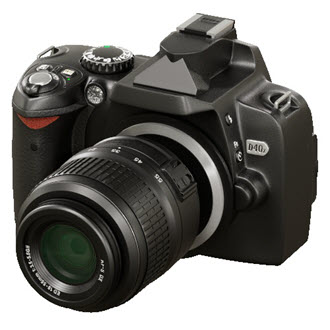
Camera Product Visualization
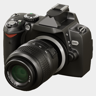
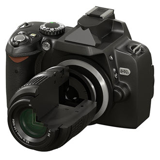
This tutorial will cover how to light, shade, and render a CAD model of a DSLR camera. It covers various styles including a product shot and illustrative styles that could be used in a product brochure. These styles include wireframe, facing_ratio (x-ray), and a toon edge. We will also cover how the utility shader can be used to create render passes for use within a compositing package and can also be useful for debugging scenes.
A DSLR camera model can be downloaded here.
Importing the CAD Data
- Start off by downloading the CAD model (link above).
- You should see the following parts in the .zip file. Unzip the data to your hard disk.
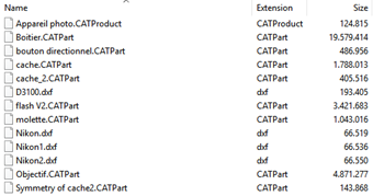
Select the files and drag them from your file explorer onto the Maya viewport. Maya will then convert the CAD geometry for you. You should see the model appear in your Maya scene (see below).
Ensure that you have the ATFPlugin.mll plugin loaded in the plug-in manager otherwise the camera geometry will not import.
The model has originated from a CAD package that works the in Z-up axis, whereas Maya defaults to the Y-up axis. Go to Preferences -> Settings -> World Coordinate System and change it to Z.
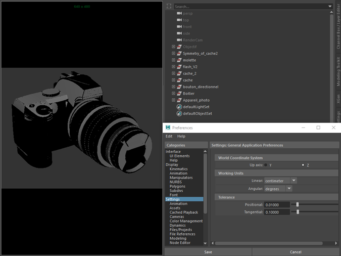
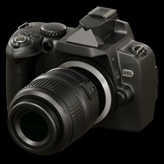
The CAD files imported in Maya. World Coordinate System: Z
Lighting
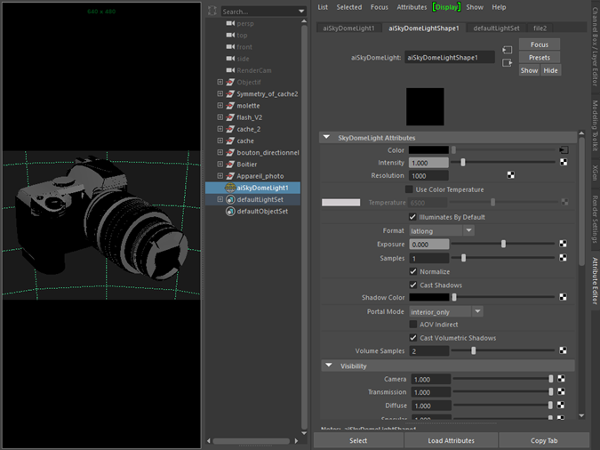
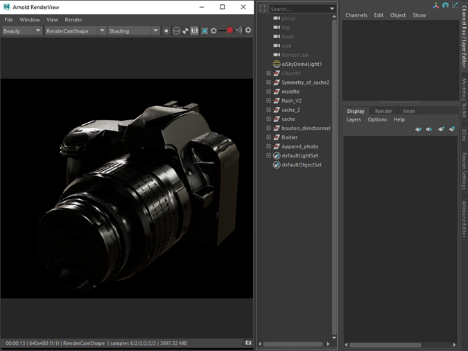
The scene is simply lit using a studio HDRI connected to the skydome_light.color
- Choose Arnold under the Create tab and click on Arnold Light. Click in the viewport to create the skydome_light.
- Rotate the skydome_light 90 degrees in X as the scene is set to Z-up.
- Reduce the camera visibility of the skydome_light to 0. We will add a separate white background later.
- Connect a file texture to the color attribute of the skydome_light and choose a suitable HDRI. An example of a studio HDRI that could be used with this scene can be downloaded here.
Choose a bitmap (HDRI) for the Texture of the skydome_light
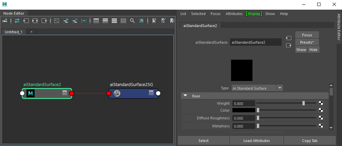
To test the lighting, we can quickly assign a standard_surface shader to the camera.
- In the Hypershade window create and assign a standard_surface shader to the camera.
- Change its base_color to black.
- Render the scene using the default Arnold sample settings. These settings are fine for IPR test rendering the scene. Do not worry about any noise in the scene at the moment. We will change the sample settings once we are happy with the lighting and shading at the end of production.
Feature Overrides: This group of switches allows you to disable a number of important rendering features. By selectively disabling some features, you can get a feel for where the renderer is spending most of the time, which helps optimizing scenes. Lighting or look-dev could be sped up by enabling ignore_textures or ignore_shaders for example. This is also useful for isolating errors and artifacts when debugging. Note that not all of these options are interactive - some of them may require the entire scene to be refreshed/exported.
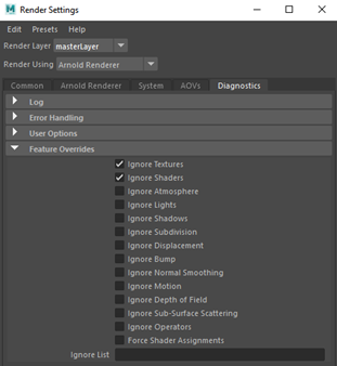
Render Settings → Diagnostics → Feature Overrides
Debug Shading: This temporarily replaces the shading applied to all objects with a variety of debugging shading modes. This is used for interactive rendering purposes only and won’t change anything in the Maya scene.
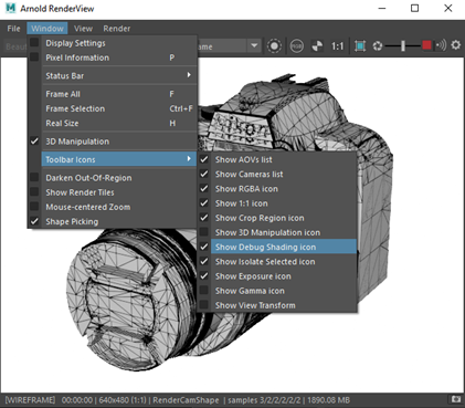
Debug shading: wireframe
A studio lighting scene can be downloaded here.
Background
Next, we need to change the background environment color to white.
- Go to Render Settings → Environment* → *Background and create a ray_switch shader.
- Change the Camera Ray Type to white.
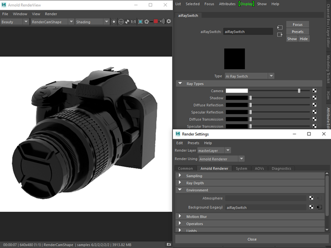
Environment -> Background -> ray_switch.camera: white
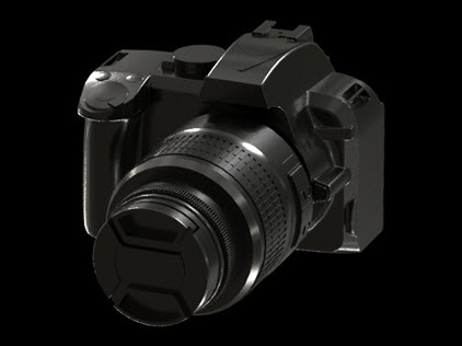 |
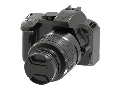 |
| Background: Color: Black (default) | Background: Color: White |
Realistic Shading
We want to create a plastic shader that can be copied and used for the main body, the leather style grip, and lens. We will also create an anisotropic metal shader for the adapter ring and glass shaders for the lens and flash.
Body
Create a standand_surface shader and assign it to the main body and lens of the camera. Change the following parameters:
- base_color : black.
- specular_roughness : 0.467.
- specular_IOR : 1.55 (plastic).
- coat_weight : 0.1
- coat_roughness : 0.3
- coat_IOR : 1.55 (plastic).
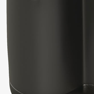
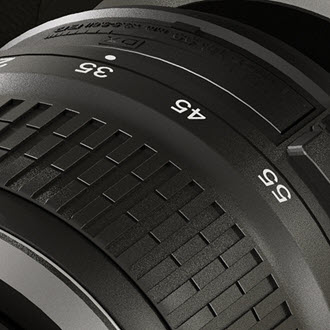
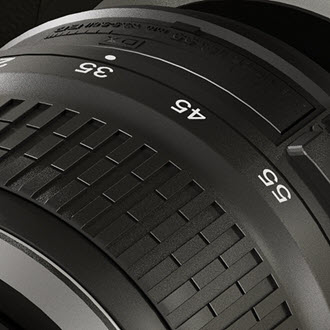
Leather Syle Bump
We can use the cell_noise shader to create a convincing leather style texture to the camera grip shader.
- Duplicate the plastic shader and assign it to the leather grip object.
- Connect a bump3d to the normal parameter of the standard_surface.
- Connect a cell_noise to the bump_map parameter of the bump3d. Using a bump 3d as opposed to bump 2d means we do not have to be concerned about the UVs of the model as it will render it in 3d object space.
- Change the pattern of the cell_noise to alligator. This will give the leather style look.
- Increase the number of octaves to 8.
- You may need to increase the scale depending on the size of your camera model. In this case, a value of 6 was used.
- Reduce the density to around 0.5.
 |
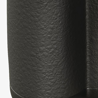 |
| Without bump | cell_noise -> bump3d |
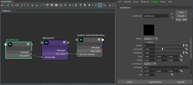
cell_noise → bump3d → standard_surface
Camera Lens Adapter Ring
We will create an anisotropic metal material that could be used for an adapter ring of a camera.
- Assign another standard_surface shader. Assign it to the metal adapter ring on the camera body and rename it to 'Metal Ring'.
- Change the base_color to a mid-gray color.
- Increase the metalness to 1.
- Increase the specular_roughness to around 0.7. Lower amounts will appear shinier.
To create the anisotropic metal effect, we will use ramp_rgb → specular_ anisotropy. We will project it using a uv_projection shader to avoid any UV issues from the CAD geometry.
Create a ramp_RGB shader and change the type to radial. Insert around five black and four white knots. Ensure that their interpolation is set to catmull-rom (smooth).
Connect it to a uv_projection shader. This is to planar project the ramp_rgb onto the metal ring.
Connect the uv_projection to the specular_anisotropy of the standard_surface shader.
You may notice faceting appears in highlights when using specular_anisotropy. It is possible to remove the faceted appearance by enabling smooth subdivision tangents (via Arnold subdiv_smooth_derivs parameter. Take into account this requires a subdivision iteration of at least one in the polymesh to work.
 |
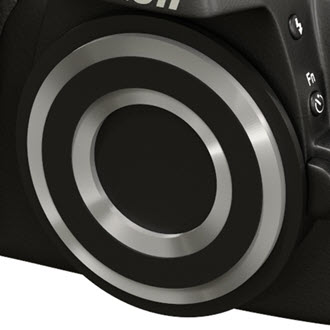 |
| Without anisotropy | ramp_RGB -> anisotropy |
anisotropic_rotation can be used to change the location of the specular_anisotropy highlight.
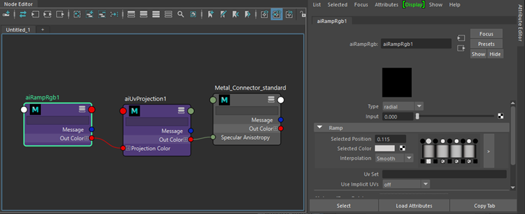
ramp_rgb → uv_projection → standard_surface
Glass Lens
- To reveal the lens first hide the lens cap (cache.1, cache2.1 and Symmetry of cache2.1.1 in the Scene Explorer window).
- Assign another standard_surface shader to the glass lens geometry (Body.8) and call it 'Lens Glass'.
- Reduce the specular_roughness to 0.
- Change the specular_IOR to 1.5 (glass).
- Increase the transmission to 1.
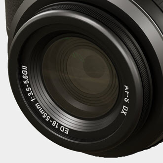
- Under thin_film, increase the thickness to around 450 and the thin_film.ior to around 1.28.
 |
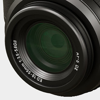 |
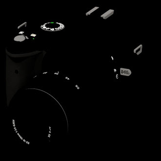
| thin_film.thickness: 0 (default) | thin_film.thickness: 454 |
Stylized Shading
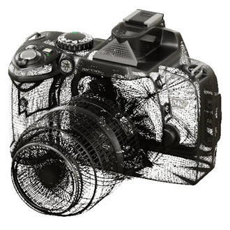
Now we will look at a variety of shading methods to create stylized renderings such as wireframe, orthographic line-art (toon), x-ray (facing_ratio) and cut away renders (clip_geo).
 |
 |
 |
 |
 |
| wireframe -> opacity | toon | facing_ratio -> opacity | utility -> toon_edge | clip_geo |
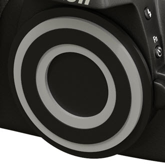
Wireframe shader
- To create a wireframe/semi-shaded look we can use the wireframe shader connected to the opacity of the black plastic shader we created earlier.
- Change the edge_type to polygons. Adust the line_width to a low amount. In this case, a value of 0.02 was used.
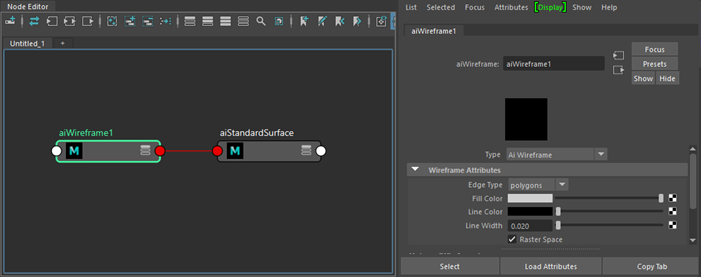
wireframe → opacity of standard_surface
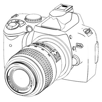
Toon shader
Assign a toon shader to all of the camera geometry. Change the following parameters:
Reduce the angle_threshold to around 10. This will give more detailed edges around the geometry.
Reduce the base_weight to 0. We are only going to use emission.
Ensure that specular_weight is 0.
Increase the emission_weight to 1.
The toon shader does not currently work with GPU. This is planned to be fixed in a future release.
To view the toon edge, you must change the filter type (sampling settings) to c ontour . Note that i ncreasing the c ontour filter width (sampling settings) value will increase render times.
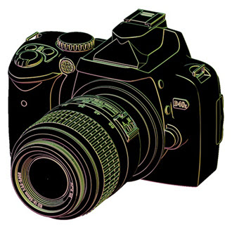
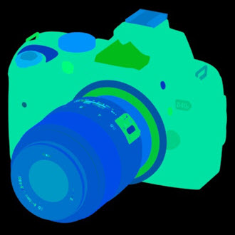
Another variation would be to connect a utility (color_mode: geometric_normal (ng)) shader to the edge_color of the toon shader (emission_weight: 0).
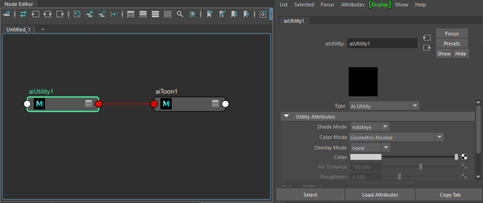
utility → toon.edge_color
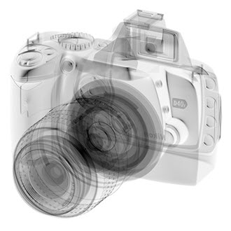
Facing Ratio shader
We can create an x-ray shading effect by using the facing_ratio shader.
- Assign a standard_surface shader and reduce all of the weights to 0.
- Create a facing_ratio shader and connect it to the opacity of the standard_surface shader.
- Reduce the bias to around 0.1.
- To further refine the effect, connect a color_correct shader in-between the facing_ratio and the standand_surface shader.
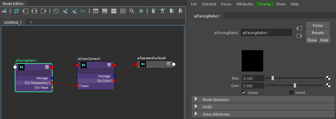
facing_ratio -> color_correct -> standard_surface
Clip Geo shader
We can use the clip_geo shader to create a cut-away shading effect in the camera model.
- Create a Box (geometry to be used for clipping and position it where you want to clip the geometry (in this case it is cutting into the lens).
- Assign a clip_geo shader to the box.
clip_geo does not currently work with GPU. This is planned to be fixed in a future release.
AOVs
AOVs are Arnold's method of rendering render passes. They provide a way to render any arbitrary shading network component into different images. For example, an artist might find it convenient to separate direct and indirect lighting contributions and later recombine them during compositing. Arnold provides built-in AOVs for outputting depth, position, and motion vectors.
Composing the Beauty AOV: The RGBA beauty AOV can be split into smaller AOVs where each contains part of the lighting. In compositing, these AOVs can then be individually modified and added together to get the full beauty AOV. More AOVs give more control in compositing, but also extra work to handle, and they take up more memory and disk space, especially combined with light groups.
Some example sets of additive AOVs for the full beauty AOV are:
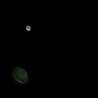
- direct, indirect, emission, background.
- diffuse, specular, coat, transmission, sss, volume, emission, background.
- diffuse_direct, diffuse_indirect, specular_direct, specular_indirect, coat, transmission, sss, volume, emission, background.
Simply adding together such AOVs is all that is needed for the beauty AOV. The albedo AOVs are not needed to reconstruct the beauty AOV but may be used for example to get just the lighting without the surface texture, by dividing diffuse by diffuse_albedo, or for denoising just the lighting while keeping the texture detail intact.
 |
 |
 |
| RGB AOV | background AOV | diffuse AOV |
 |
 |
 |
| specular AOV | specular_indirect AOV | transmission AOV |
- To access AOVs go to the AOVs tab in the Arnold Render Settings window.
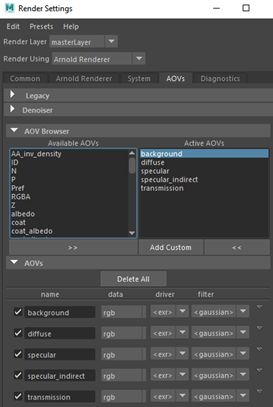
Arbitrary Output Variables (AOVs) Manager. Create diffuse, specular, specular_indirect, transmission, and background AOVs.
- Choose the file Type. The default EXR is normally recommended, however, for this example we will use Png as we will simply be rebuilding the RGBA beauty in Photoshop.
- Render out the AOVs to disk either from the Render View window or via Render -> Batch Render.
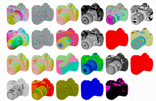
Cryptomatte: Cryptomatte AOVs can also be used to create ID mattes for compositing later on. Cryptomatte creates ID mattes automatically with support for motion blur, transparency, and depth of field. Names, object namespaces, and material names can be used to organize ID mattes in the scene.
 |
 |
 |
| crypto_asset | crypto_object | crypto_material |
Compositing in Photoshop
- Open the AOVs that we saved to disk in Photoshop.
- Drag and drop the layers from each Png onto the Background image layer as indicated in the image below.
- Change the blending layer mode to Linear Dodge (Add) for each layer. You should see the final beauty layer.
To create a correct rebuild of the RGBA beauty AOV you must use add/plus operations in the composite. If you use screen or multiply you will get an incorrect result.
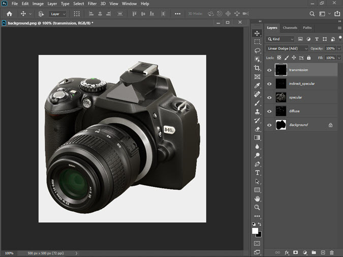
AOVs opened in Photoshop and layered together using Linear Dodge (Add)
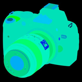
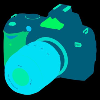
Utility Color Modes: The utility shader is a general 'all-purpose' utility node shader that can also be used to create passes for use within a compositing package. It can also be useful for debugging scenes. For example, the geometric_normal position could be used to re-light the model in post-production.
The various color modes used by the utility shader
Final Render Settings
For final frame rendering, we will need to increase some sample settings.
Remember to check your AOVs if you are unsure where the noise is coming from.
- Select the skydome light and increase the number of samples to 3 or 4. This should clean up a lot of the noise in the shadows.
 |
 |
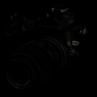
| Skydome light samples: 1 (default) | Skydome light samples: 4 |
- Increase the number of Camera (AA) to around 5. This will improve the general image quality.
- Even, though we have increased the Camera (AA) samples there is still some noise on the lens (visible in the specular AOV). We can reduce this further by increasing the number of specular samples to 4. Note that your render times will be longer when increasing this value.
 |
 |
| Specular samples: 2 (default). Specular noise visible on top of lens. | Specular samples: 4. Noise has been improved. |
That's it. You have reached the end of the tutorial. Well done!