4.3. Prestress Beam Definition (Simple)
Subjects Covered
- Prestress beam
- Define material properties
- Define beam
- Sizing prestress beam
- Define prestress beam section
Outline
The section of a 21m long prestressed concrete beam and insitu concrete slab is shown below.

The prestressed beam is a standard Y beam the size of which is to be determined and is cast using grade C40/50 concrete. The age of the precast concrete at transfer is 4 days and is 60 days old when the insitu concrete is placed. The 200mm thick insitu slab is 2m wide and constructed using grade C32/40 concrete. Standard wire pre-stressing strands are used; each having an area of 150mm2 and a nominal diameter of 16 mm. The characteristic strength of each tendon is 1861MPa and the relaxation at 1000 hours is set to a value of 2.5%. Tendons are initially located in all default manufacturers’ locations as shown above. Save the file as “My EU Example 4_3.sam” for use in a later example.
Procedure
- Start the program and create a new beam using the menu item File | New | Create from Template... and select “EU Pretensioned” from the “My Templates” list.
-
Use the menu item File | Titles... to set the beam title to “Prestress Beam - Simple” with a sub-title of “Example 4.3”. Also set the Job Number to “4.3” and add your initials to the Calculated by data item if necessary. Click on ✓ OK to close the Titles form.
Modify Materials Loaded from the Template
Next we will change the material properties defined in the template.
- In the Materials navigation window select the material “MP5:” from the navigation tree, which is the Structural Steel material defined in the template and use the “-“ toolbar button, of the navigation window, to delete this redundant material.
-
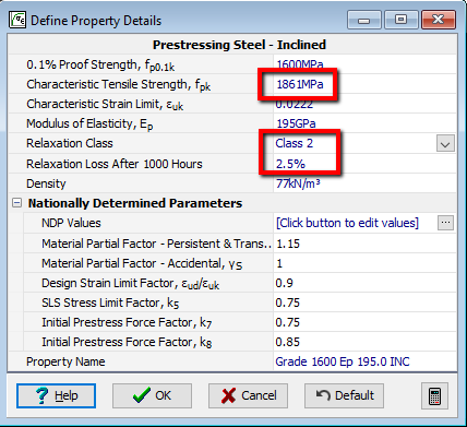
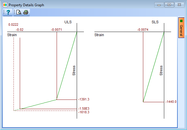
Select the material “MP4” from the navigation tree to open the prestress material properties. Change the Characteristic Tensile Strength, fpk to “1861MPa”. Ensure Relaxation Loss After 1000 Hours is set to “2.5%” and the Relaxation Class is set to “Class 2” before closing the form with ✓ OK.
The next step is to define the geometry of the beam.
- In the Design Beam Navigation window select “Beam Definition” in the navigation tree.
-
In the Beam length field, enter a value of “21m”. Make sure Cross section is is set to “uniform” and Location is is set to “Interior beam”.
Suggest Section Size
Next we will get the program to suggest a sizing for the beam cross section.
-
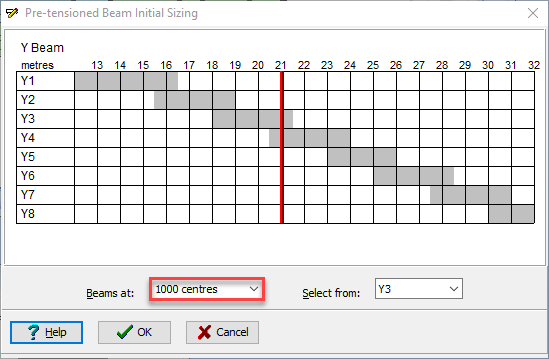
Click on the Suggest size of drop down and select “Y beam” from the list of options. This will open the Pre-tensioned Beam Initial Sizing form.
-
Click on the Beams at drop down and select “2000 centres”. The graph will update to show Y7 as the best initial size for the cross section. Click ✓ OK to select this size.
Define Slab
The next step is to define the slab.
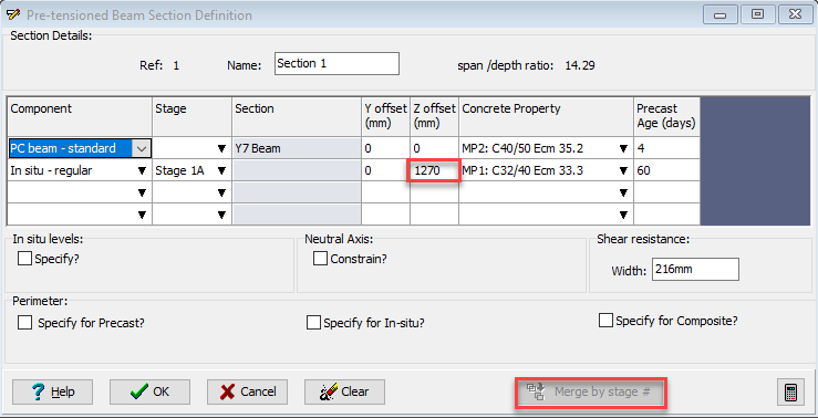
- Click on the Define drop down in the Pre-Tensioned Beam Definition form and select “Section” from the list of options. This will open the Pre-tensioned Beam Section Definition form where you will see the Y7 cross section defined in the previous step.
- Click on the Component column in the second row of the table and select “In situ – regular”. This will open the Define Precast Beam Component form. The Shape Reference will be set to “Rectangle” already so enter “2000mm” in the width field and “200mm” in the depth field then click ✓ OK.
-
Ensure the Z offset for the slab is set to “1270” (input this data and press Enter on the keyboard if it is not). Click on the Merge by stage # button so that the program will remove the overlapping material for the two section components.

-
Check that the Concrete Property for the beam is set to grade C40/50 and the age at transfer is 4 days. The Concrete Property for the slab is set to grade C32/40 and the age of the precast beam when this is placed is 60 days. Click on the ✓ OK button to close the Pre-tensioned Beam Section Definition form.
-
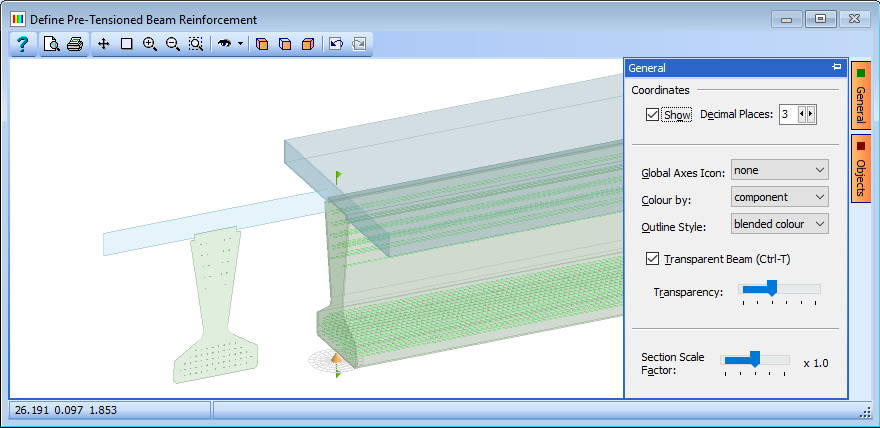
In the Define field dropdown select “Reinforcement” to open the Define PreTensioned Beam Reinforcement form and then in the graphics window toolbar select the
 icon to show an isometric view in which a three dimensional representation of the reinforcement/tendons can be seen. Parameters for this view can be controlled on the orange General tab at the side of the graphics window.
-
Click on ✓ OK to close the Define Pre-tensioned Beam Reinforcement form.
- Click on ✓ OK to close the Pre-tensioned Beam Definition form.
- Click on the main menu item File | Save as... to save the file as “My EU Example 4_3.sam”.
- Close the program.
Summary
This example shows how to enter a simple pretensioned prestressed beam into Autodesk® Structural Bridge Design. Particular emphasis is placed on the suggested initial beam size based on the span and spacing of the beam.
It should be noted that the suggested size is just a recommendation and need not be used. In this case the precast beam section shape is defined by selecting from the full list or defining the shape manually.