4.5. Reinforced Concrete Beam Definition
Subjects Covered
- Reinforced concrete beam
- Parametric shape
- Join button
- Y and Z offset
- Soffit face
- Soffit profile
- Define reinforcement
- Locate bar by 2 covers
- Snap mode
- Superimposed bars
- Reinforcing bar shape;
Outline
Create a uniform RC beam 30m long using the section shown below. The material for the beam is grade C40/50 concrete. Ensure that the soffit is defined in the section.
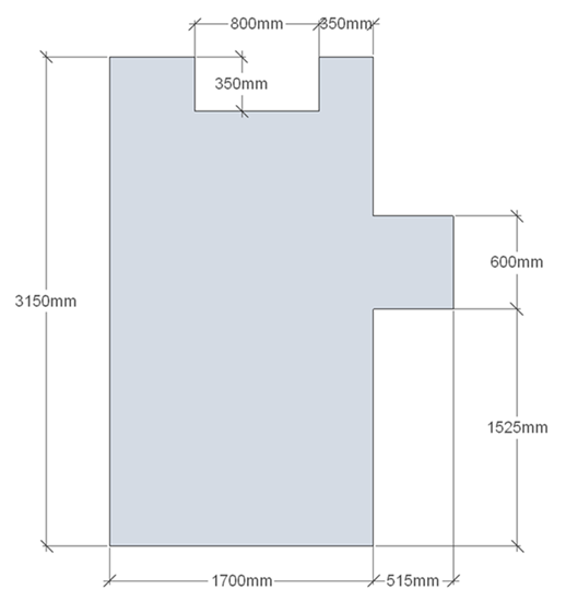
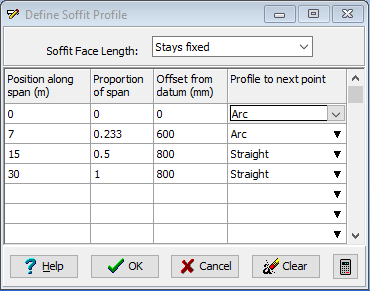
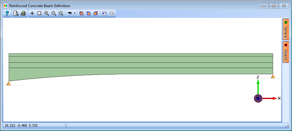
The beam has a soffit profile as shown below .

| Soffit Coordinates | Point | |
|---|---|---|
| A | 0.00 | 0.00 |
| B | 7.00 | 0.60 |
| C | 15.00 | 0.80 |
| D | 30.00 | 0.80 |
Place 4 rows of 40mm diameter bars in the bottom face, parallel to the soffit and two rows in the top face (on the underside of the rebate). Cover to the outer faces of the concrete should be 50mm with 50mm between rows and each row should contain 15 bars.
Procedure
- Start the program and create a new beam using the menu item File | New | Create from Template... and select “EU RC” from the “My Templates” list.
- Use the menu item File | Titles... to set the beam title as “Reinforced Concrete Beam” with a sub-title of “Example 4.5”. Also set the Job Number to “4.5” and add your initials to the Calculated by data item if necessary. Click on ✓ OK to close the Titles form.
-
In the Design Beam navigation window, select Beam Definition to open the Reinforced Concrete Beam Definition form. Enter a value of “30m” in the Beam Span field. Click on the Define drop down menu and select “Section” from the list. This will open the RC Beam Section Definition form.
Define Cross Section
-
On the first row of the table, click in the Component drop down menu and select “Parametric shapes” from the list. This will open the Define Reinforced Concrete Beam Component form. Select “Rectangle” from the Shape Reference drop down menu. Enter a value of “1700mm” in the width field and “2800mm” in the depth field. Click on the ✓ OK button to close the Define Reinforced Concrete Beam Component form.
- On the second row of the table, click in the Component drop down menu and select “Parametric shapes” from the list. Using the Define Reinforced Concrete Beam Component form, create a “Rectangle” of 550mm width and 350mm height. Click on the ✓ OK button to close the Define Reinforced Concrete Beam Component form.
-
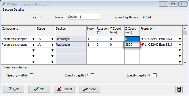
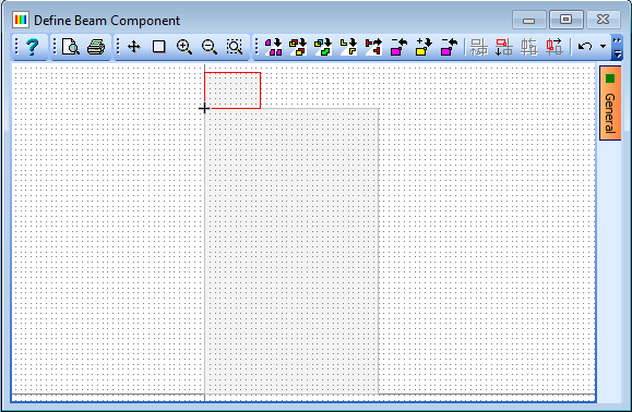
On the second row of the table, enter a value of “2800mm” in the Z Coord field and press the ‘Enter’ key. Click on the
 button in the graphics window toolbar.
-
On the second row of the table, click in the Component drop down menu and select “Parametric shapes” from the list. Using the Define Reinforced Concrete Beam Component form, create a “Rectangle” of 350mm width and 350mm height. Click on the ✓ OK button to close the Define Reinforced Concrete Beam Component form.
-
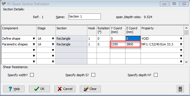
On the second row of the table, change the Y Coord value to “1350mm” and the Z Coord value to “2800mm” and press ‘Enter’ on the keyboard. Click on the
 button in the graphics window toolbar.
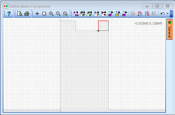
-
On the second row of the table, create another “Rectangle” of 515mm width and 600mm height using the same method as step 6. Change the Y Coord value to “1700mm” and the Z Coord value to “1525mm” and press the ‘Enter’ key. Click on the
 button in the graphics window toolbar.
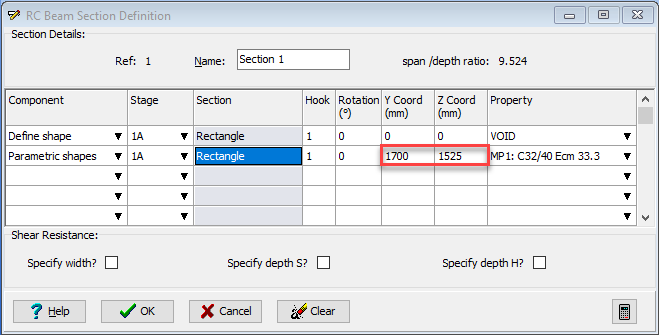
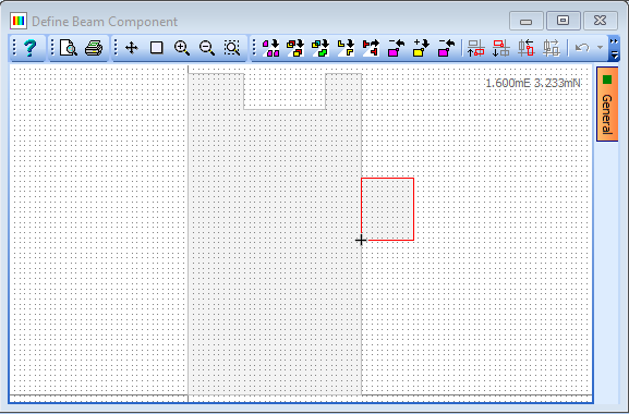
-
Click on the bottom face of the section in the graphics window. The face will change to a dashed line. This line type is used to indicate a continuous face. Click on the bottom face again to change it to a solid, bold line. This tells the program that the face is a soffit face and will follow the soffit profile of the beam.
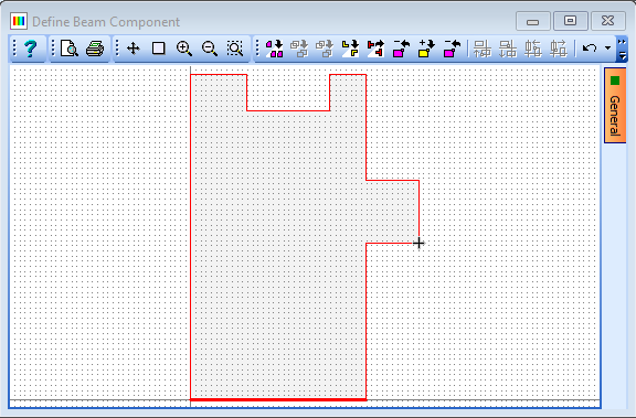
Finally, select Grade C40/50 concrete from the Property drop down menu. Click on the ✓ OK button to close the RC Beam Section Definition form.
Define Soffit Profile
-
Click on the Define drop down menu and select “Soffit Profile” from the list. This will open the Define Soffit Profile form.
- On the second row of the table, click in the Position along span field and enter a value of “7.0m”. On the same row, click in the Offset from datum field and enter a value of “600mm”.
- On the third row, enter a value of “15.00m” in the Position along span field and “800mm” in the Offset from datum field.
- On the fourth row enter a value of “800mm” in the Offset from datum field. On the first row, click in the Profile to next point drop down and select “Arc” from the list.
- Click on the ✓ OK button to close the Define Soffit Profile form.
Define Reinforcement
As a first estimate, 6 rows of reinforcement, 4 rows at the bottom and 2 rows at the top of the section will be defined along the entire span.
- Click on the Define drop down menu and select “Reinforcement” from the list. This will open the Define RC Beam Reinforcement form together with two graphics views, one showing the elevation and one the cross section of the beam.
- Click and hold the green arrow marker in the graphics window and drag it to the support at the left hand end of the beam. Click on the “+” button near the bottom of the form to open the Define Reinforcement form. The outermost bars in each row of reinforcement will first be defined with appropriate cover.
-
Click on the Generate drop down and select “1 bar by 2 covers”.
-
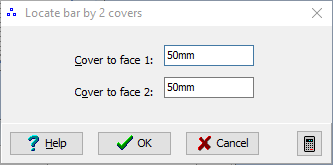
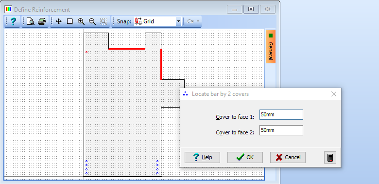
Set the Diameter field to “40mm” then click on the bottom and left hand faces of the cross section. This opens the Locate bar by 2 covers form. Leave both covers set to “50mm” and click ✓ OK. Repeat the process, this time clicking on the bottom and the right faces and use the same cover.
- Next click on the bottom and left hand faces and enter covers of “50mm” and “140mm”. Repeat this using the bottom and right hand faces, entering covers of “140mm” and “50mm”.
- Repeat these steps, entering covers of “50mm” and “230mm”, and “230mm” and “50mm”. Finally repeat these steps, entering covers of “50mm” and “320mm, and “320mm” and “50mm”.
There are now 8 bars defined for the bottom of the section.

This process needs to be repeated for the top two rows of bars.
-
-
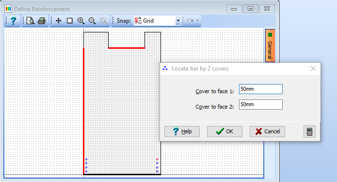
Click on the left hand face and the lower middle face on the top of the section and set both covers to “50mm”.
-
Next, click on the lower middle face and the right hand face and set both covers to “50mm”.
-
Repeat these steps, entering covers of “140mm” and “50mm” for the left hand side and “50mm” and “140mm” for the right hand side. There will now be 4 bars defined at the top of the section.

The next step is to fill in the remaining bars between the layer pairs.
-
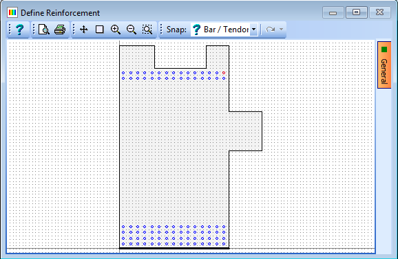
Click on the Generate drop down and select “Draw bars” from the list. Set No. Of bars to “15”, then click on the Snap drop down on the graphics toolbar and select “Bar/Tendon”. Click on the bottom left bar then click on the bottom right bar on the cross section. The program will draw 15 equally spaced bars between the two selected bars.
-
Repeat this process for the remaining 5 rows of bars. The cross section will now look like this:
-
Click on ✓ OK on the Define Reinforcement form. The program will produce the following warning message:
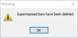
This is because the program defines bars at each of the locations where the mouse was clicked. These 12 bars need to be removed so click OK to remove them and define the beam reinforcement.
-
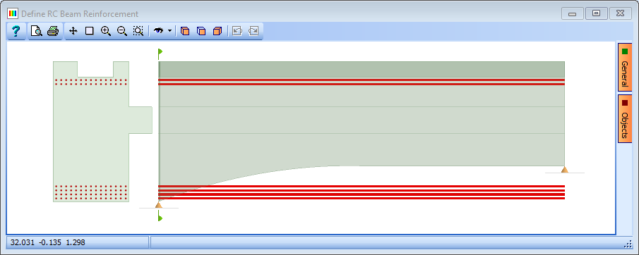
The program assumes reinforcing bars are horizontal. The side elevation will look like this:
-
It is required that the bottom bars should run parallel with the soffit. To do this, draw a box around all the bottom bars in the cross section and click on the Edit reinforcement attributes button
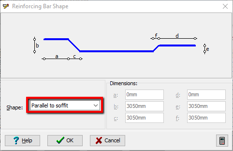
 at the bottom of the form. Click on the “Set Bar Shape” button on the form that appears. This opens the Reinforcing Bar Shape form.
-
Click on the Shape drop down and select “Parallel to soffit”. The elevation will automatically update to show the reinforcement in the correct location. Click ✓ OK to close the Reinforcing Bar Shape and Edit Reinforcement Attributes form.
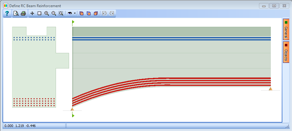
Click ✓ OK to close the Define RC Beam Reinforcement form.
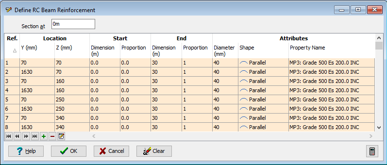
Click ✓ OK to close the Reinforced Concrete Beam Definition form.
-
Clicking on the
 icon when the Define RC Beam Reinforcement form is open shows an isometric view in which a three dimensional representation of the reinforcement can be seen. Parameters for this view can be controlled on the orange General tab at the side of the graphics window.
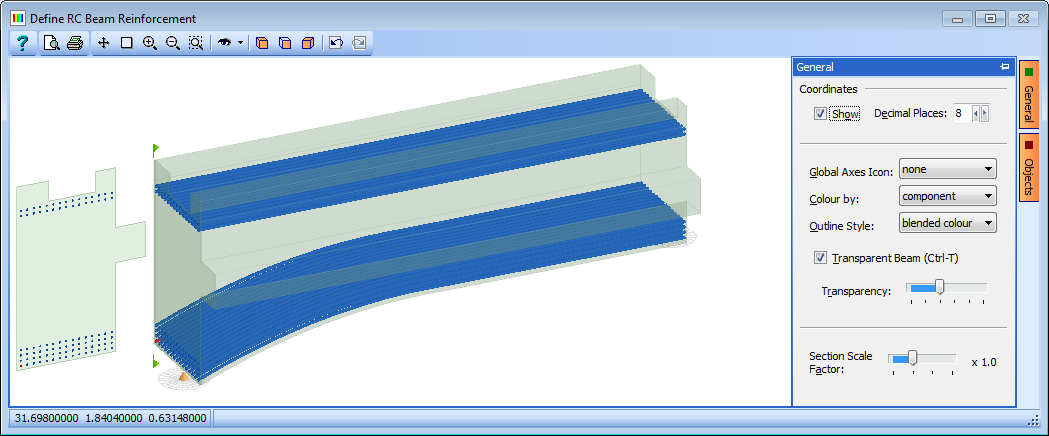
The beam definition is now complete so we will save the beam for use in a later example.
- Click on the File | Save As... menu item to open the Save File form. Change the filename to “My EU Example 4_5.sam” and click on the Save button to save the data file.
- Close the program.
Summary
In this example we have defined a reinforced concrete section making extensive use of the join command to create a complex section shape from a series of rectangles. We then defined the soffit profile of the beam. Finally, we defined 6 layers of reinforcement with the reinforcement at the bottom following the curved soffit profile.