4.1. Steel Composite Beam Definition
Subjects Covered
- Steel composite beam
- outer beam
- rolled steel UB
- concrete haunch
- concrete edge
- edge cast with slab
Outline
Create a simply supported composite steel/concrete beam 26m long with a uniform section as shown below.
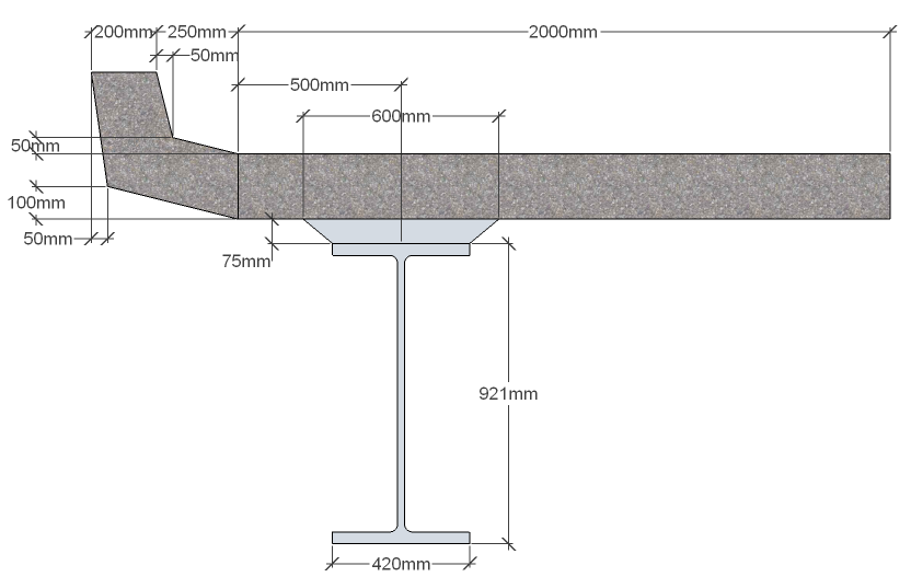
The steel beam is a standard Universal beam 914x419x388 and has standard default steel material properties. The 200mm thick concrete slab is grade C32/40 concrete. The concrete edge geometry has been pre-defined and is stored in a section library, which can be imported. It is structural and it is cast separately from the slab. The edge will need offsetting to place it in the correct position. Save the file for use in a later example.
Procedure
- Start the program and create a new beam using the menu item File | New | Create from Template... and select “EU Steel Composite” from the “My Templates” list.
-
Use the menu item File | Titles... to set the beam title as “Composite steel/concrete Beam - Simple” with a sub-title of “Example 4.1” and a Job Number of “4.1”. Also add your initials to the Calculated by data item if necessary. Click on ✓ OK to close the Titles form.
Define Beam
- In the Design Beam navigation window select the “Beam Definition” item in the navigation tree.
- Click in the Span field and enter a value of “26m”. Click on the Location is drop down menu and select “Outer beam” from the list.
- Click on the Define drop down menu and select “Section” from the list to open the Composite Beam Section Definition form. Click in the Component drop down menu on the first row of the table and select “Rolled Steel UB” from the list.
-
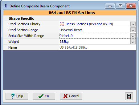
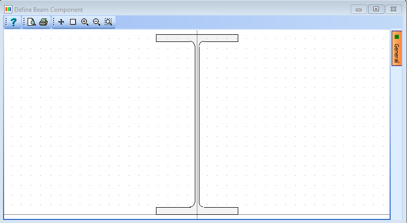
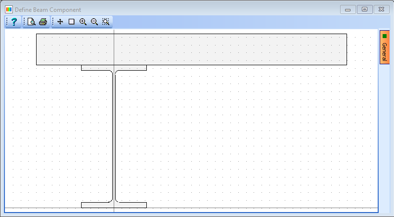
This will open the Define Composite Beam Component form. Ensure that the Steel Sections Library dropdown is set to “British Sections”. Click on the Serial Size Within range drop down menu and select “914×419” from the list. Click on the ✓ OK button to close the Define Composite Beam Component form.
-
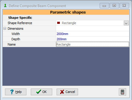
Click in the Component drop down menu on the second row of the table and select “Concrete Slab” from the list. This will open the Define Composite Beam Component form. Click in the width field and enter a value of “2000mm”. Click in the depth field and enter a value of “200mm”. Click on the ✓ OK button to close the Define Composite Beam Component form. Click in the Slab Details Y offset field and enter a value of “0.5m”.
Add Haunch and Edge Detail
-
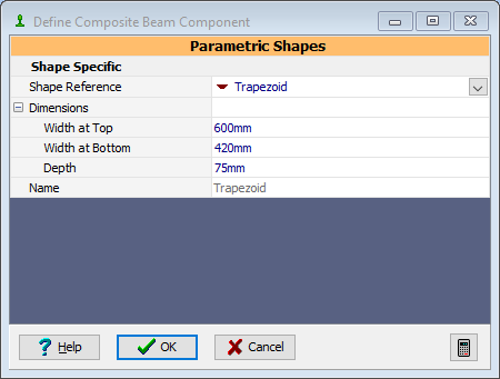
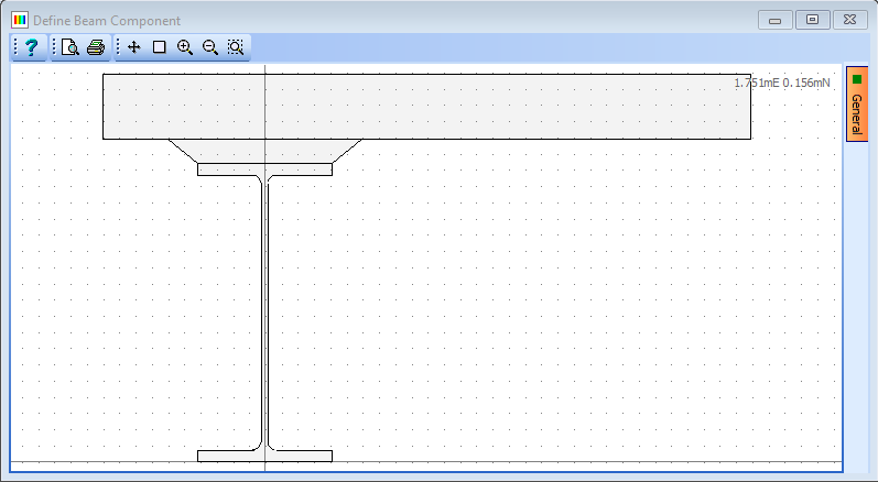
Click in the Component drop down menu on the third row of the table and select “Concrete Haunch” from the list. This will open the Define Composite Beam Component form. Click in the width at top field and enter a value of “600mm”. Click in the width at bottom field and enter a value of “420mm”. Click in the depth field and enter a value of “75mm” Click on the ✓ OK button to close the Define Composite Beam Component form.
-
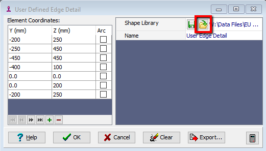
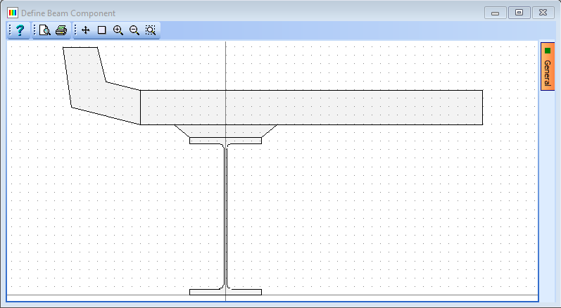
Click in the Component drop down menu on the fourth row of the table and select “Concrete Edge” from the list. This will open the User Defined Edge Detail form.
-
Click on the Retrieve button and open the supplied file “EU Example 4_1 Edge Details.lib”. There is only one shape in this library file so select it and click on the ✓ OK button on this form and another form that may appear. The edge detail is not located correctly in the section but this can be done by setting the offsets in the Composite Beam Section Definition form.
- Close the User Defined Edge Detail form with the ✓ OK button.
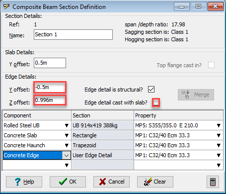
- Enter a Y offset: of “-0.5” and a Z offset: of “0.996”.
-
Uncheck the Edge detail cast with slab? checkbox.
-
Ensure that the 3 concrete components have the C32/40 concrete property assigned to them. Click on the ✓ OK button to close the Composite Beam Section Definition form.
-
Click on the ✓ OK button to close the Define Composite Beam form.

-
In the main menu select File | Save As... to open the Save File form.
- Change the filename to “My EU Example 4_1.sam” and click on the Save button to save the data file.
- Close the program.
Summary
In this example we have defined a steel composite beam which includes a concrete haunch and a concrete edge detail. The edge detail was imported from a user library file but could easily have been generated by entering the coordinates of the shape vertices directly into the table. Note that the materials for each section component were not explicitly defined but these materials were previously defined in Chapter 1 of this manual when defining the templates. Different materials could have been selected here if they had been additionally defined.