5.2 Prestressed Beam Design
Subjects Covered
- Prestressed beam design
- Erection loads
- Generate beam loads
- Beam dead load
- Temporary support loads
- Apply negative loads to beams
- Temporary construction loads
- Beam span increments
- Constructions loads
- Remove loads
- Superimposed dead loads
- Import live loads
- Absolute shears
- Eurocode temperature profiles
- Tendon layout optimisation
- Shear resistance
- Shear width
- Shear link requirements
- Transverse reinforcement requirements
Outline
A composite pre-tensioned pre-cast beam and concrete slab is shown below. The beam is an internal beam of a simply supported bridge deck of 21m span and the 2m wide concrete slab is cast in one. The dimensions of the beam can be found in example 4.3.
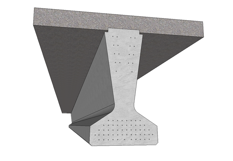
The bending and shear effects due to dead load and superimposed dead load (2.5kN/m) are created by using the “Generate” feature in the program. During construction the beam is initially supported on temporary supports at 1m from the beam ends. There is also a temporary load of 1.4kN/m over the length of the beam which represents temporary construction loads and the water in wet concrete. This load and the temporary supports are removed once the concrete has hardened.
Max live load bending (with associated shears) and shear effects (with associated moments) have been prepared in an external ASCII file as envelopes.
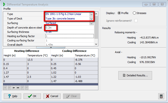
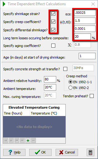
There are no secondary effects due to differential temperature and shrinkage, as the beam is statically determinate, but the primary stresses need to be included for both, where appropriate. The temperature profile to be applied to the section is in accordance with Differential Temp Fig 6.2, with a surfacing finish 100mm thick. The shrinkage strain for the concrete is to be set to -0.00025 with 20% of this occurring before the insitu slab is cast. The differential shrinkage strain should be -0.0001 and the creep coefficient set to 1.5.
It is required to design the required tendon layout with appropriate debonding so that SLS and ULS design criteria for bending moments and stresses are met during transfer, beam erection and during normal use. Shear link spacing in the beam also needs to be determined to resist both transverse and longitudinal shear forces. The reinforcement grade for the shear links is the same as that for the main reinforcement and the vertical shear is resisted by the precast beam only. For longitudinal shear it can be assumed that the interface surface is Type 2.
All design is to Eurocodes.
Procedure
-
Start the program and open the data file “EU Example 4_3.sam” created in section 4.
-
Use the menu item File | Titles... to set the title as “Prestressed Concrete Beam” with a sub-title of “Example 5.2”.
-
Also change the Job Number: to “5.2” and add your initials to the Calculated by data item if necessary.
-
Click ✓ OK to close the titles form.
Define Erection Loads
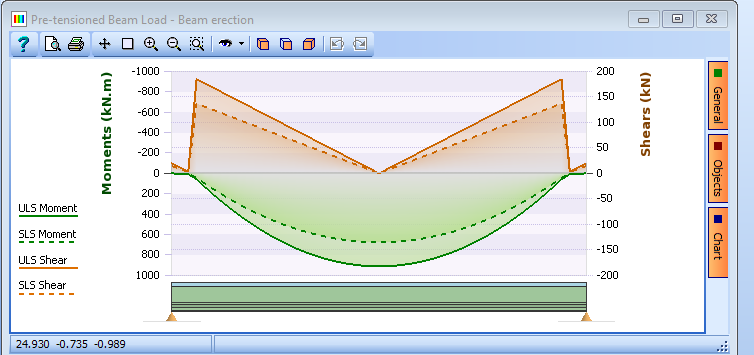
Next we will define erection of beam loads using the “Generate” facility to include two extra components; one for the temp 1kN/m and the other for the support loads (upwards).
-
To add a this erection load effects open the Define Pre-Tensioned Beam Loads form using the
 button, in the toolbar of the navigation window, and select Beam Loads | Beam Erection.
 -
Click the Generate button and then click on “Yes” on the confirmation form that appears. The Generate Beam Loads form will now open.
The program automatically calculates the dead load for the beam and adds it as the first component of the generated load, called “Beam dead load”.
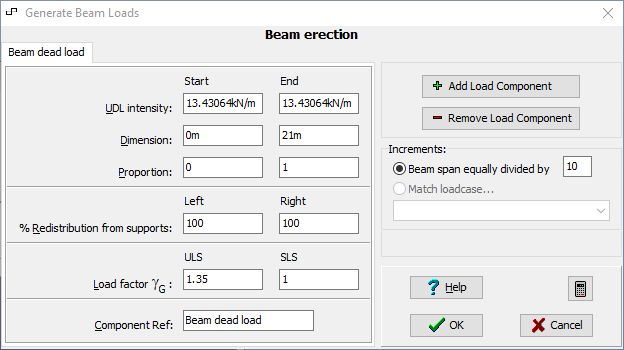
This load needs to be applied equally to the two temporary support locations. The UDL intensity is 13.4306kN/m which applies a total load of 282.0426kN to the beam. Since the program can’t apply a point load to a beam, this needs to be applied using two, 100mm long UDLs. The equivalent applied UDL intensity over a 100mm length is 1410.213kN/m.
-
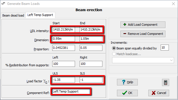
Click the Add Load Component button and enter the UDL Intensity Start and End as “1410.213kN/m”.
-
Set Start Dimension to “0.95m” and the End Dimension to “1.05m".
-
Change the ULS and SLS Load Factors to “-1.35” and “-1” respectively to make this an upward load and set the Component Ref. to “Left Temp Support."
-
Click the Add Load Component button and repeat the process (remembering to make ULS and SLS Load Factors negative), this time setting the Start Dimension to “19.95m”, the End Dimension to “20.05m” and the Component Ref. to “Right Temp Support."

Finally, the temporary load due to construction and water in the wet concrete needs to be defined.
-
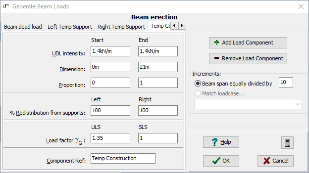
Click on the Add Load Component button again and enter the UDL Intensity Start and End as “1.4kN/m”. Leave all the other fields at their default values and set the Component Ref. to “Temp Construction."
-
In the Increments section, set Beam span equally divided by to “50” then click ✓ OK to close the Generate Beam Loads form.
The Define Pre-tensioned Beam Loads form will now show the total load applied by the four load components. Note that by default the calculated shears are Absolute Shear values but can be changed to Real Shear using the radio button at the bottom of the Define Pre-Tensioned Beam Loads form. This may be necessary to ensure that all the different load case shears are of the same type.
-
Close the Define Pre-Tensioned Beam Loads form with the ✓ OK button.

Define Construction Stage 1 Loads
The next step is to define the load effects for construction stage 1.
-
Open a new Define Pre-Tensioned Beam Loads form using the
 button in the toolbar of the navigation window, and select Beam Loads | Construction Stage 1A.
 -
Click on the “Generate” button to open the Generate Beam Loads form. The program automatically calculates the UDL intensity for the self weight of the slab so just click ✓ OK to create the effects and close the form.
-
Close the Define Pre-Tensioned Beam Load form with the ✓ OK button.
Remove Temporary Loads and Supports
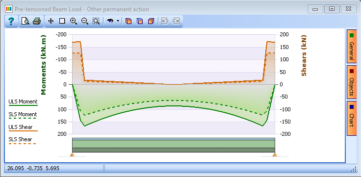
The next step is to define a load case to remove the effects of the temporary loads and supports.
-
Open a new Define Pre-Tensioned Beam Loads form using the
 button in the toolbar of the navigation window, and select Beam Loads | Other permanent action then click on the “Generate” button.
 -
Set the UDL Intensity Start and End as “1410.213kN/m”.
-
Set Start Dimension to “0.95m” and the End Dimension to “1.05m”.
-
Change the ULS and SLS Load Factors to “1.35” and “1” respectively and set the Component Ref. to “Rm Left Temp Sup”.
-
Click the Add Load Component button and repeat the process, this time setting the Start Dimension to “19.95m”, the End Dimension to “20.05m”.
-
Change the ULS and SLS Load Factors to “1.35” and “1” respectively and set the Component Ref. to “Rm Right Temp Sup”.
-
Finally it is necessary to remove the temporary construction loads. Click on the Add Load Component button again and enter the UDL Intensity Start and End as “1.4kN/m”.
-
Change the ULS and SLS Load Factors to “-1.35” and “-1” respectively and set the Component Ref. to “Rm Temp Const”.
-
In the Increments section, set Beam span equally divided by to “50” then click ✓ OK to close the Generate Beam Loads form. The Define Pre-tensioned Beam Loads form will now show the total load applied by the three load components.
-
In the User Name: field enter “Rm temp const Load” to assist with identification in the navigation window before closing the Beam Load form with the ✓ OK button.
Define Surfacing and Live Loads
The next step is to define the SDL surfacing loads.
-
Open a new Define Pre-Tensioned Beam Loads form using the "+" button in the toolbar of the navigation window, and select Beam Loads | Surfacing then click on the “Generate” button to open the Generate Beam Loads form.
-
Set the UDL Intensity Start and End as “2.5kN/m” then click ✓ OK to generate the load effects.
-
Close the Define Pre-Tensioned Beam Loads form with the ✓ OK button.
The next step will be to import some results from a separate live load analysis by using a text file that is formatted in a certain way. This file may have any number of load effect cases but in this case it will contain just two.
-
Click the “Import”
 toolbar button from the navigation toolbar.
 -
Select the supplied file “EU Live Loads.sld” and click Open. This will import loads into the ‘Traffic gr1b-gr5 – for Bending design’ and ‘Traffic gr1b-gr5 - for Shear design’ design load cases and will appear in the navigation tree. Select one of these to check the format.
It can be seen that the shear effects are all positive, which means absolute values are assumed. This is why it is important to ensure that the other load cases are absolute shears.
-
Click ✓ OK to close the Define Pre-tensioned Beam Loads form.
Enter Temperature Profile and Shrinkage and Creep Parameters
A differential temperature profile needs to be defined and values for the shrinkage and shear parameters need to be specified. These are entered from the analysis form.
-
Click the
 Analyse Beam toolbar button to open the Pre-tensioned Beam Analysis form.
 -
Click in the Analyse for: field and select “Differential temperature primary stress” to open the Differential Temperature Analysis form.
-
In the Type field select “EN 1991-1-1-5 Fig 6.2 Non-Linear” from the list of options and set the Type of Deck field to “Type 3b: concrete beams”. Then set the Surface thickness to “0.1m” before closing the form with the ✓ OK button to accept this profile.

-
Next, click the Set parameters for: drop down and select “Time dependant effect calculations” from the list of options. This will open the Time Dependant Effect Calculations form.
-
Set the Shrinkage strain to “0.00025”, the Long term losses occurring before composite to “20%”, the Differential shrinkage to “0.0001” and the Creep coefficient to “1.5”. (Tick the relevant tickboxes to activate these fields).
-
Click ✓ OK to save the parameters.
-
Set the value in the Exposure: field to “XD1”.
Tendon Optimisation
The next step is to design the required tendon layout, such that it will comply with stress limits for all design cases. The tendon optimisation algorithms in the program can be used to do this to achieve the most economical solution.
-
Click on the Tendon Optimisation button on the Pre-tensioned Beam Analysis form and click ✓ OK on the information form. This will open the Tendon Optimisation form.
-
Tick the Applied Load tick box and the Debond tick box. For this example the Locations / Limit field will be set to “4”.
-
Use the default values for all the other fields on the form and click on the Design Optimised Layout button.
-
After a short while a warning message will appear indicating that the limiting strains in the concrete slab at ULS do not comply as they are primarily in compression. Note this warning and continue using the ✓ OK button on the warning message. The program will now consider a series of tendon arrangements to come up with the optimised layout for the beam.
At the end of the optimisation, the program produces an error message and provides a summary on the right hand side of the form. This indicates that the software cannot find a solution with this configuration.

-
Click ✓ OK to close the error message then click the ✓ OK button to close the optimisation form. Click ✓ OK to close the Pre-tensioned Beam Analysis form.
In order to resolve the first warning and get a solution we will try increasing the strength of the precast concrete material and adjusting the strain limit of the cast in place concrete.
-
Change the navigation window to Materials and select the 1st material. In the Ultimate Compressive Strain, εcu field enter “0.002."
-
Click ✓ OK on the Define Property Details form to save the change.
-
Select the 2nd material in the navigation tree.
-
In the fck field, change “40” to “50” to increase the strength.
-
Click ✓ OK to save the change.
-
Change the navigation window to Design Beam and click on the
 Analyse Beam toolbar button to re-analyse the beam.
 -
Click on the “Tendon Optimisation” button and adjust the Debonding Limits: per Jump: to “30%”, then click on the “Design Optimised Layout” button to re-run the tendon optimisation with the new material properties.
This time the tendon optimisation will complete without an error message. Take note of the warning message – but the prestress is adjusted automatically anyway to satisfy this.
-
Click ✓ OK on the warning message and click ✓ OK to close the Tendon Optimisation form.
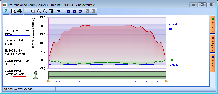
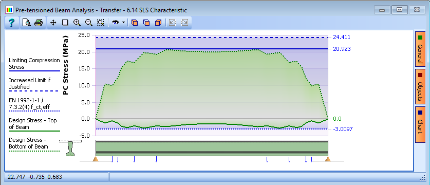
It is noted that the compressive stresses at transfer are shown in red – which indicates a failure. This is because that in some locations the stresses exceed the basic limiting compressive stress, but, the code allows an increase in this if it can be justified (eg increased QA at a precast yard). In addition, there has been no consideration of any enhancements that could be obtained, for example, by considering the concrete being cured at a higher temperature. We can now investigate this.
-
In the Set parameters for: field select “Time dependent effect calculations."
-
In the resulting data form set the Ambient temperature: field to “28” and close the form with ✓ OK (again dismissing the warning message).
Check Stresses for other design situations
The next step is to check the stresses for other design combinations (for example, beam erection, construction stages and live load cases). In this example the stresses will be checked for the one live load combination we have, however, this should be checked at “t = ∞” and “t = 61”, just after the structure is complete” to take account of time dependant effects.
The graphical display is a good way to make these checks, but the graphics will display only one of four conditions at a time (i.e. min top stress, min bottom stress, max top stress or max bottom stress). So for one live load combination we should make a total of 8 graphical checks.
-
Click the Analyse for: drop down and select “Bending for gr 1b-gr5 1”. There are no secondary temperate effects as the structure is simply supported so dismiss the confirmation notice with the Yes button. Also dismiss the warning message as before.
-
On the Pre-tensioned Beam Analysis form set Time Considered: to “t = ∞” and the Fibre Stress: field to “Minimum top”.
-
Set the Results Point of Interest to “20” and Note the stresses and repeat for the other three Fibre Stress: conditions.
-
Set Time Considered: to “t = 61” days and the Fibre Stress: field to “Minimum top”. Note the stresses and repeat for the other three Fibre Stress conditions.
T=Inf fibre =Min top

T=Inf fibre =Min bottom
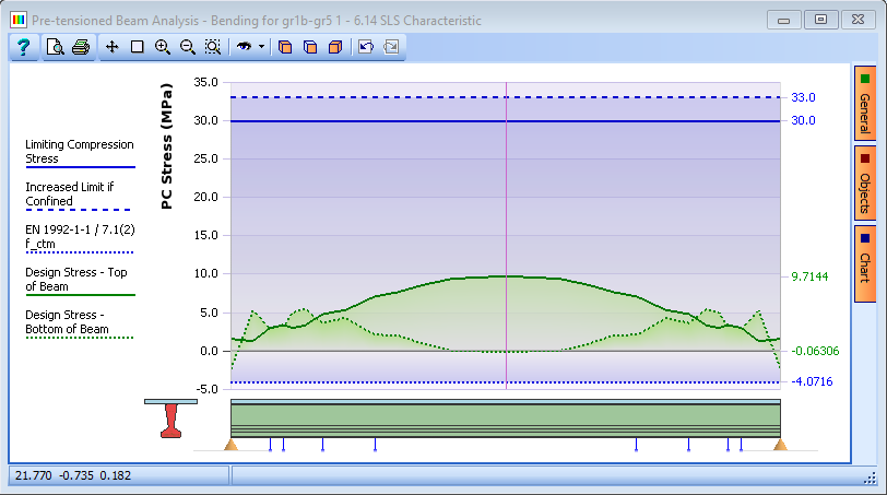
T=Inf fibre =Max top
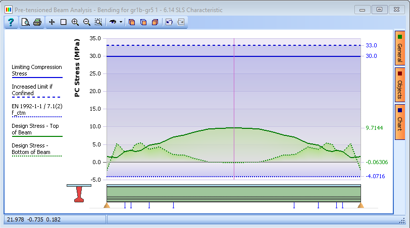
T=Inf fibre =Max bottom
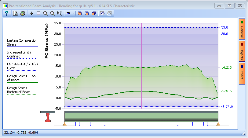
T=61 days fibre =Min top
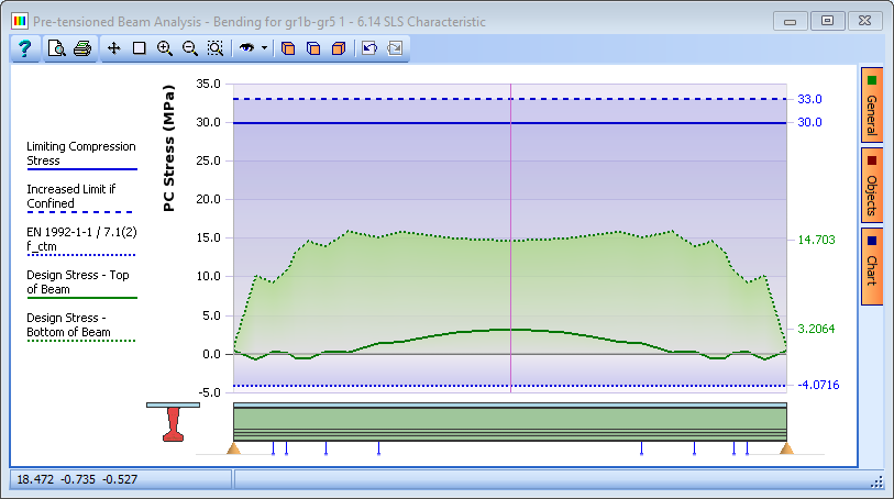
T=61 days fibre =Min bottom
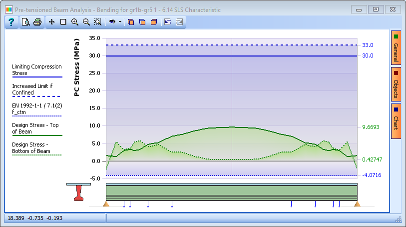
T=61 days fibre =Max top
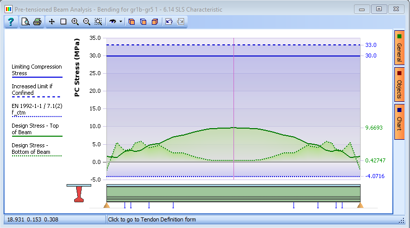
T=61 days fibre =Max bottom
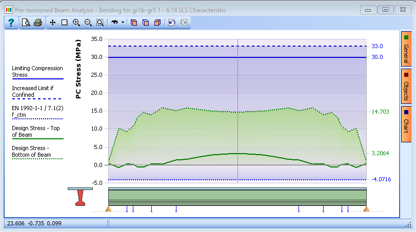
Although the stresses don’t appear to change much in this example the differences become more marked when the structure is continuous where secondary effects become more significant.
-
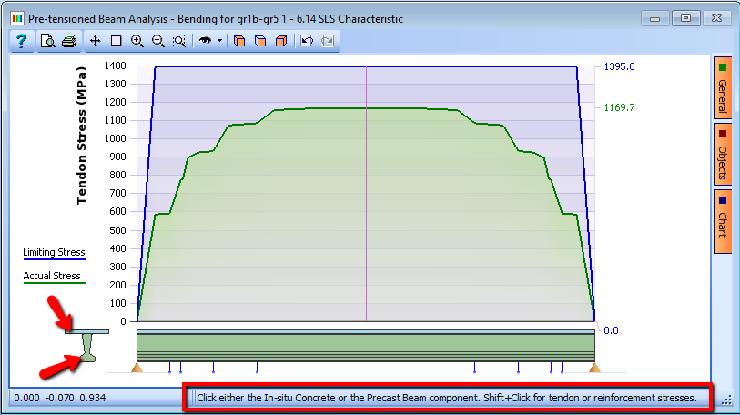
In the graphics window click on the slab in the small section to display the slab stresses and if the shift key is held down at the same time then reinforcement or tendon stresses are displayed.
Design for Shear
The next step is to check the beam for shear, both at SLS for web shear cracking and at ULS for direct vertical shear.
-
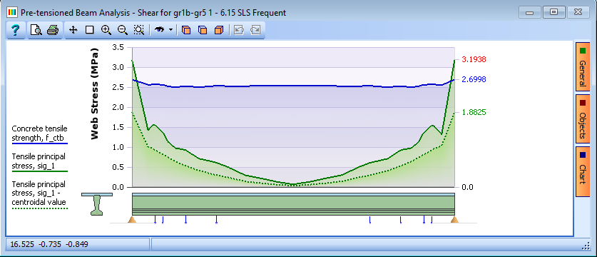
Click on the Analyse for drop down and select “Shear for gr 1b-gr5 1”. If a warning message appears dismiss it because we will set the limit state to SLS Frequent anyway as it is a prestressed beam.
-
Set the Limit State field to “SLS Frequent” and note the reduction in the tensile principle stress effect.
-
You will notice that the beam appears to fail at the very ends but in reality this will be well within the cast in place diaphragms so web shear cracking should not be a problem.
-
Now change the Limit State: field to “ULS Persistent/Transient” to carry out the calculations for vertical shear where we will determine the requirement for shear links.

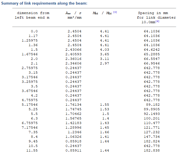
The calculations show that even with the default minimum strut angle the section will adequately carry the design shear effects giving a minimum link spacing of about 160mm (this can be seen by clicking on the Results button and examining the table in the results viewer). However, these requirements need to be merged together with the longitudinal shear link requirements so, it may be more advantageous to increase the strut angle. This will have the effect of increasing the number of shear links required for direct shear, but reducing the requirement on any additional longitudinal steel (even if in this example no additional longitudinal reinforcement is required at any angle). This will be better in most cases as the requirement for direct shear links and interface shear links will be closer so the addition will be minimised. To achieve this we need to adjust the shear calculation parameters.
-
In the Set Parameters for: field select “Shear calculations”, from the list, which will open the Design Data for Shear form.
-
Change the value in the Angle between strut and beam axis field to 45.
-
Also, in the Surface Condition: field, for Interface shear, change the value from “Smooth” to “Rough”, to determine the correct cohesion and friction factors, and then change it to “User Defined” to activate these factors before closing the form with the ✓ OK button.
-
Click the Results button and scroll down to the bottom of the Results Viewer. Note that the values of MRd divided by MEd are always greater than 1 (see note 3 at the bottom of the Results Viewer) which means that no additional longitudinal reinforcement is necessary for shear requirements.
Shear Link Requirements for both Direct and Interface Shear
Now that the beam design passes for the direct shear force case, the next step is to design the shear links in the beam merging the requirements from the direct and interface shear cases.
-
Click on the Analyse for field and select “Interface shear for gr1b-gr5 1” from the drop down list.

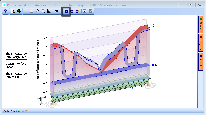
The interface shear requirement is the red dashed line and the interface shear resistance supplied by the links defined for direct shear is the solid blue line, so it can be seen that additional links are required only in the areas where the red line is above the blue line.
-
Set the design section location to the left hand end (point 1) and click on the Results button. Scroll down to the bottom of the results so you can see the reinforcement requirement.

-
When the analysis form is open the results graphs can be displayed in a 3D isometric window by clicking on the
 3D view icon on the graphics window:
-
Click the File | Save As... menu item. Set the file name to “My EU Example 5_2.sam” and click the “Save” button.
-
Close the program.
Summary
In this example we have taken a prestressed beam created in a previous example and applied load to it for a series of design load cases. We have also carried out a tendon optimisation then checked the beam for a series of design criteria.