5.3 Reinforced Concrete Beam Design
Subjects Covered:
- Reinforced concrete
- Modify length
- Import loads
- ULS design
- Minimise reinforcement
- Curtail bars
- SLS design
- Shear link design
- 3.1.2 of EN 1992-1-1
Outline
A reinforced concrete beam is shown below.
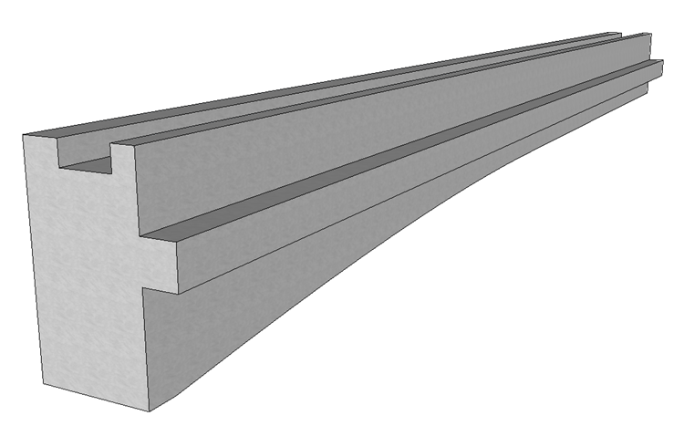
The dimensions of the original beam can be found in Example 4.5. The beam will be modified to reduce the length from 30m to 29.82m. We will then import some loads from an external file and carry out a detailed design of the beam in the following order:
- Check the beam at ULS for both sagging and hogging cases.
- Modify the reinforcement to provide adequate moment resistance.
- Curtail the reinforcement and remove bars to minimise the quantity of reinforcement whilst still having sufficient moment resistance for both sagging and hogging at ULS at all points along the beam.
- Design the shear links
- Check the beam at SLS for both sagging and hogging cases.
- Check the beam with the concrete cylinder strength at 14 days in accordance with clause 3.1.2 of EN 1992-1-1.
Procedure
-
Start the program and open the data file “EU Example 4_5.sam” in section 4.5.
-
Use the menu item File | Titles... to set the title as “Reinforced Concrete Beam Design” with a sub-title of “Example 5.3”.
-
Set the Job Number to “5.3” and add your initials to the Calculated by field.
-
Click ✓ OK to close the Titles form.
Modify Beam Length
The beam file which was put together in Example 4.5 is 30m long as a generic beam for use on a scheme. In this example we are going to use the same beam profile for a slightly different span of 29.82m.
-
In the Design Beam navigation window select “Beam Definition” to open the Reinforced Concrete Beam Definition form.
-
Change the value in the Beam span field from “30m” to “29.82m” and press ‘Enter’ on the keyboard. The program opens the following confirmation form:
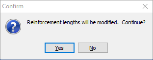
-
Click Yes and the program will modify the length of the beam and move the soffit locations to the same proportional position.
-
Click ✓ OK to close the beam definition form.
Import Loads
-
The next step is to import some loads created in a line beam analysis. Click on the Import Loads from SLD file
 toolbar button in the navigation toolbar which will open a file browser.
 -
Select the file “EU 29.82m beam right span.sld” and click on the “Open” button.
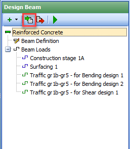
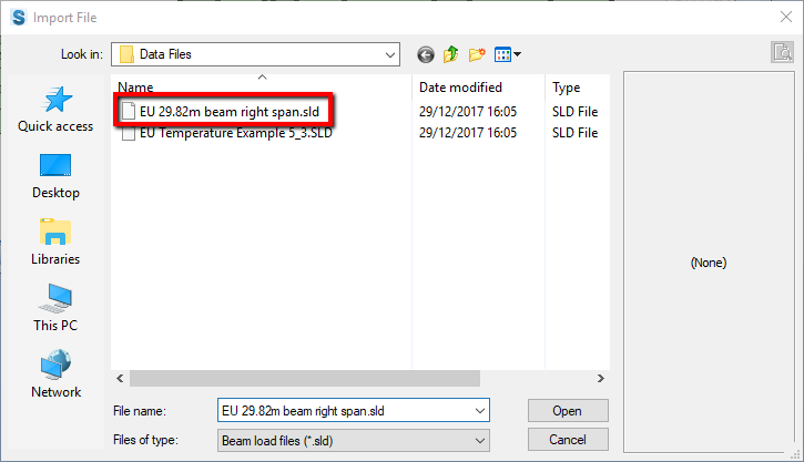
The program will import the loads in the file into the following design load cases:
- Construction stage 1A
- Surfacing 1
- Traffic gr1b-gr5 – for Bending design 1
- Traffic gr1b-gr5 – for Bending design 2
- Traffic gr1b-gr5 – for Shear design 1
Repeat the last two steps, this time selecting the file “EU Temperature Example 5_3.sld”. This file contains data for:
- Differential Temperature Heating
- Differential Temperature Cooling
The loads imported from the file can be reviewed by selecting the appropriate design load case from the navigation window tree. Click Cancel on the form to close any Define Reinforced Concrete Beam Load form left open after this review.
Design for ULS
Now that the loads have been imported into the design beam, a design check for Ultimate Limit State moments can be carried out.
-
Click on the
 Analyse Beam navigation window toolbar button to open the Reinforced Concrete Beam Analysis form.
 -
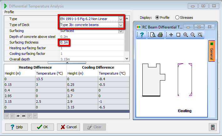
In the Analyse for dropdown select “Differential Temperature primary stresses” which will open the Differential Temperature Analysis form.
-
Set Type to be “EN1991-1-5 Fig.6.2 Non-Linear” and the Type of Deck to be “Type 3b: concrete beams”. Also check that Surface Thickness is 0.1m before clicking ✓ OK to close the form.
-
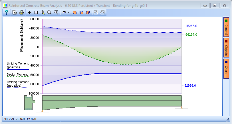
Click on the Analyse for drop down and select “Bending for gr1b-gr5 1” from the list.
-
Make sure the Limit State option is set to “ULS Persistent/Transient."
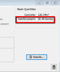
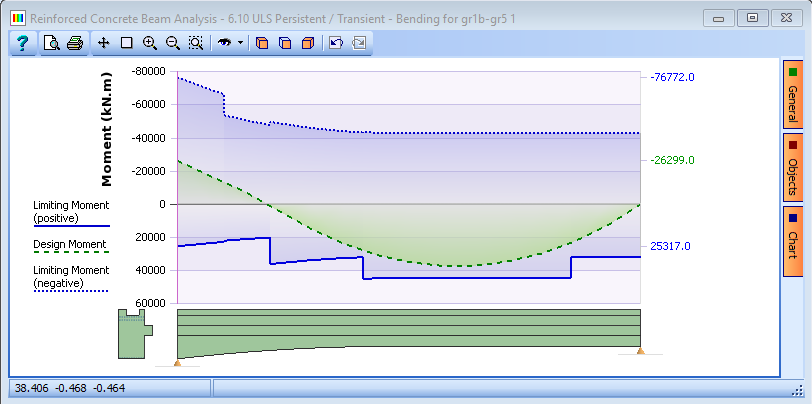
The graphical results show the design moment line in green which means the beam design passes for the positive (sagging) moment case. Looking at the top right of the form, we can see that this design of beam requires 26.49 tonnes of reinforcement.
-
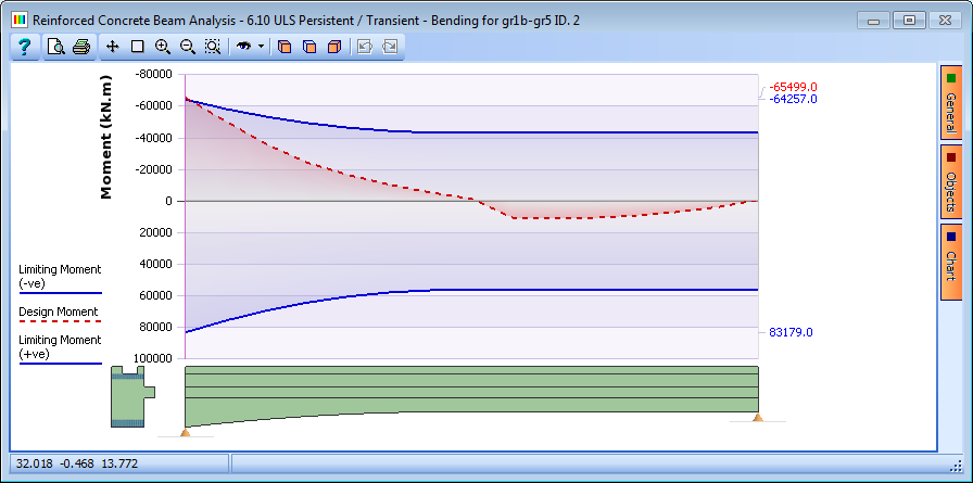
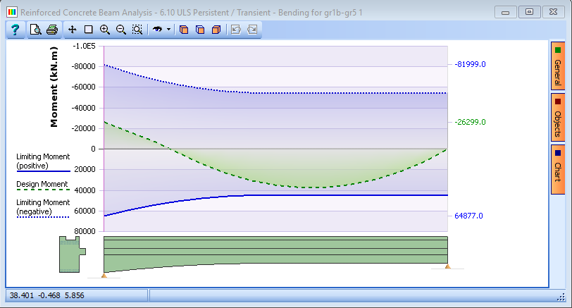
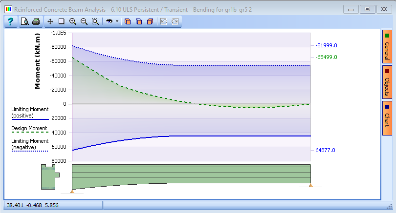
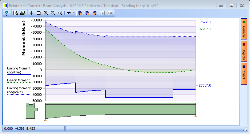
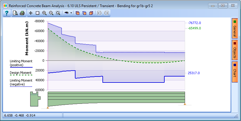
The next step is to check the negative (Hogging) moment case. Click on the Analyse for drop down and select “Bending for gr1b-gr5 2” from the list. The graphical results will update and show the following plot:
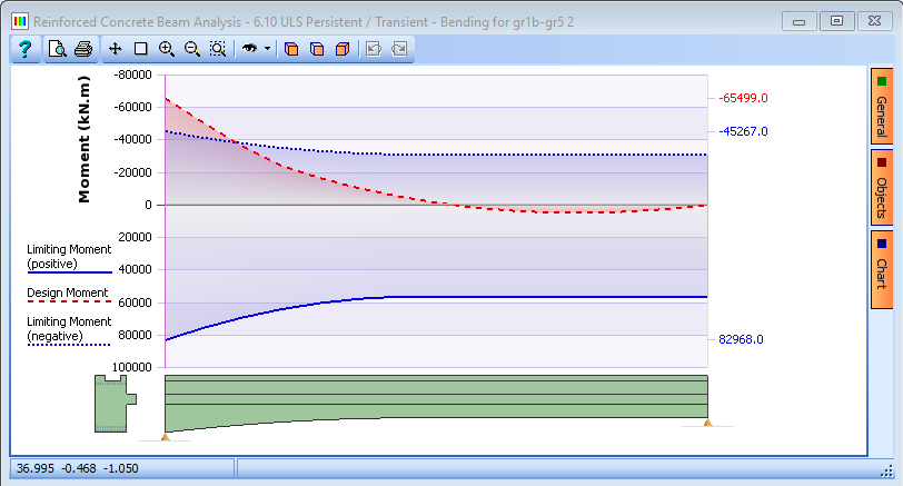
The design moment curve is shown in red, indicating that there is insufficient reinforcement at the top of the beam at the left end.
The reinforcement needs to be modified to increase the negative resistance (Hogging) moment.
-
Click anywhere on the beam elevation to open the Define RC Beam Reinforcement form together with the associated graphics windows.
-
We will start by adding a third layer of reinforcement to the top of the beam. First of all drag the red section line on the elevation with the mouse, holding the left mouse button down, to the left end of the beam.
-
Click the “+” button near the bottom of the form. This will open the Define Reinforcement form.
-
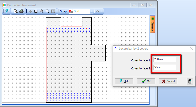
Click on the Generate drop down and select “1 bar by 2 covers”.
-
Set the Diameter field to “40mm” then click on the left hand face and the lower middle face on the top of the section. This opens the Locate bar by 2 covers form.
-
Set the covers to “230mm” and “50mm” then click ✓ OK.
-
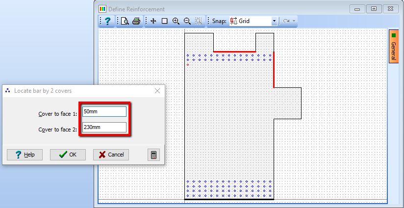
Next, click on the lower middle face on the top of the section and the right hand face and set both covers to “50mm” and “230mm” then click ✓ OK.
The next step is to define the remaining bars in the new layer.
-
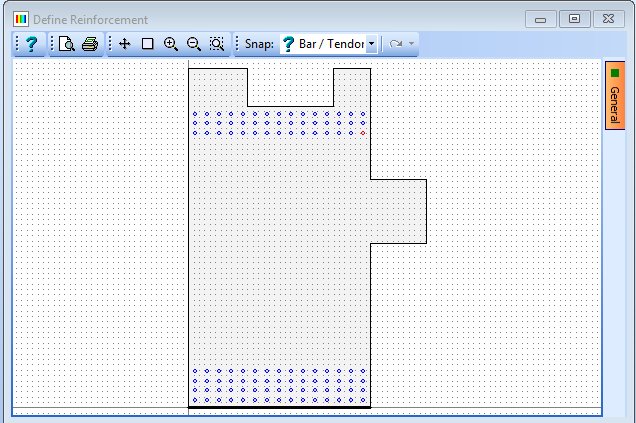
Click on the Generate drop down and select “Draw bars” from the list.
-
Set No. Of bars to “15” then click on the Snap drop down on the graphics toolbar and select “Bar/Tendon”.
-
Click on the bottom left bar then click on the bottom right bar on the cross section. The program will draw 15 equally spaced bars between the two end bars.
-
Click ✓ OK to close the Define Reinforcement form then click ✓ OK on the warning message which appears.
-
Finally, click ✓ OK to close the Define RC Beam Reinforcement form and return to the beam analysis.
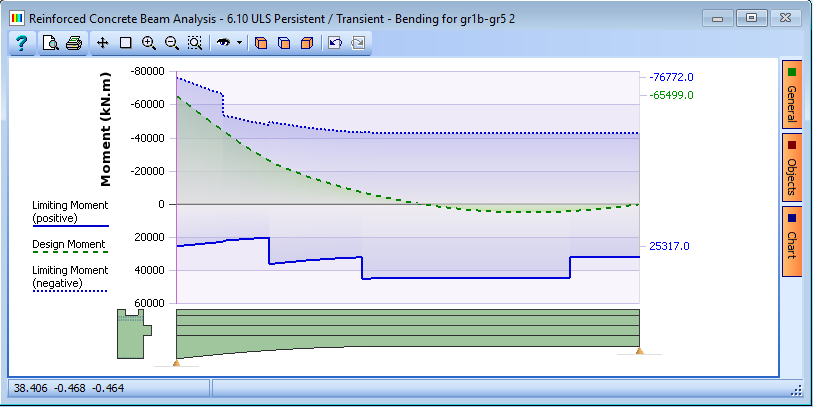
The graphical results show that the negative resistance moment is still inadequate (but not by much).
This can be remedied by adding a further layer of reinforcement at the top of the beam.
-
Click anywhere on the beam side elevation in the graphic window to open the Define RC Beam Reinforcement form together with the associated graphics windows.
-
Click on the “+” button near the bottom of the form. This will open the Define Reinforcement form.
-
Click on the Generate drop down and select “1 bar by 2 covers”.
-
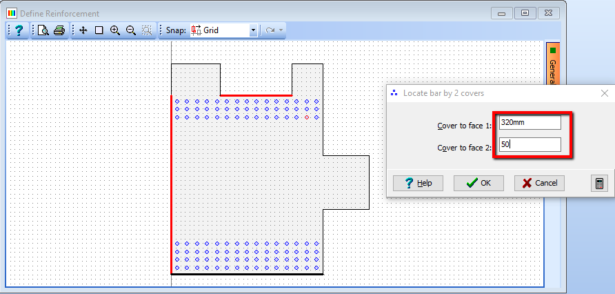
Set the Diameter field to “40mm” then click on the left hand face and the lower middle face on the top of the section. This opens the Locate bar by 2 covers form.
-
Set the covers to “320mm” and “50mm” then click ✓ OK.
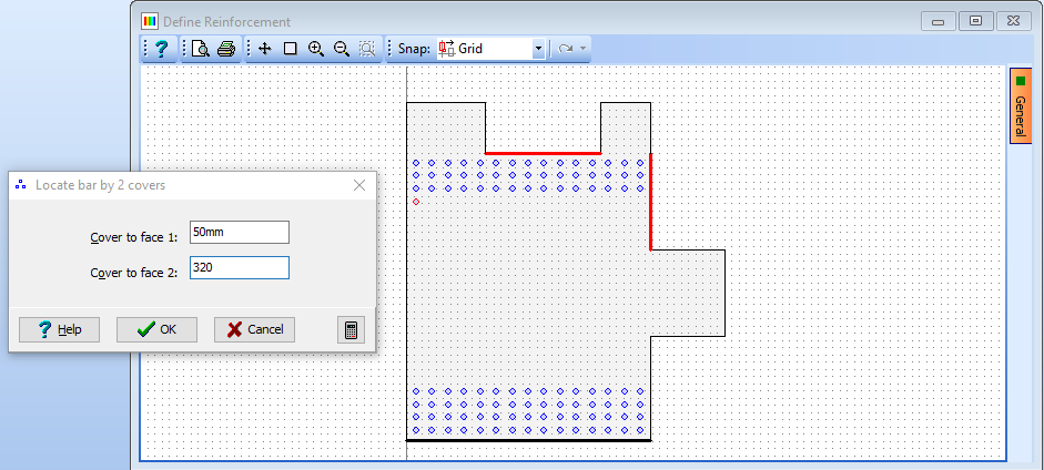
-
Next, click on the lower middle face on the top of the section and the right hand face and set both covers to “50mm” and “320mm” then click ✓ OK.
The next step is to define the remaining bars in the new layer.
-
Click on the Generate drop down and select “Draw bars” from the list. Set No. Of bars to “15” then click on the Snap drop down on the graphics toolbar and select “Bar/Tendon”.
-
Click on the bottom left bar then click on the bottom right bar on the cross section. The program will draw 15 equally spaced bars between the two end bars.
-
Click ✓ OK to close the Define Reinforcement form then click ✓ OK on the warning message which appears.
-
Finally, click ✓ OK to close the Define RC Beam Reinforcement form and return to the beam analysis.
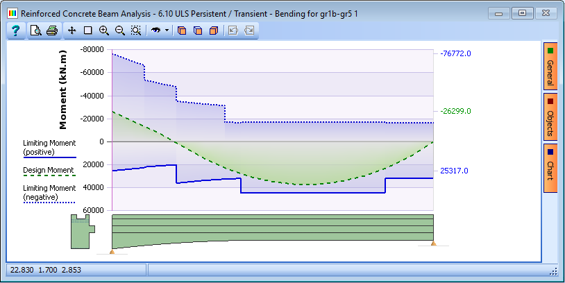
The graphical results show that the beam now has sufficient top reinforcement.

The next stage in the design is to optimise the reinforcement arrangement to reduce the quantity of steel. This initial working arrangement has 35.32 tonnes of reinforcement.
-
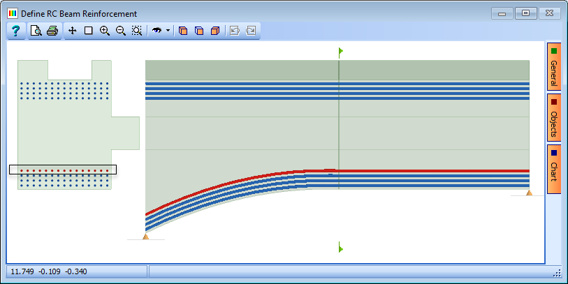
In the Analyse for: dropdown select “Bending for gr1b-gr5 2”. It can be seen that there is excess capacity in the sagging resistance so the quantity of bottom reinforcement can be reduced.
-
Click anywhere on the beam side elevation to open the Define RC Beam Reinforcement form.
-
In the beam section draw a box around the top layer of bars in the bottom of the beam; this will select them and turn them red.
-
Click on the “-” button at the bottom of the table and this will remove the layer of bars.
-
Click ✓ OK on the Define RC Beam Reinforcement forms. Checking the results for both sagging and hogging cases, where it can be seen that the beam still has sufficient resistance and the reinforcement quantity has reduced to 30.9 tonnes.
This is a far more efficient arrangement of reinforcement so we can begin to curtail the bars to optimise the required reinforcement still further.
-
Click anywhere on the beam side elevation to open the Define RC Beam Reinforcement form.
-
Draw a box around the top row of the bottom reinforcement group.
-
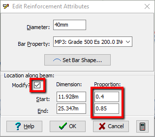
Click on the ‘Edit reinforcement attributes’ button near the bottom of the form. This will open the Edit Reinforcement Attributes form. To modify the start and end locations of the bars, tick the Modify check box and enter proportions of “0.4” and “0.85” for Start and End in the form.
-
Click ✓ OK on both forms and check the results for both cases again. Both cases need to be checked as adjusting the bottom reinforcement may have an effect on both positive and negative resistance moments. There is still sufficient reinforcement which has been reduced to 28.47 tonnes.

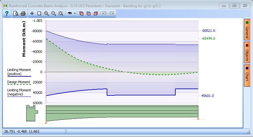
However, the bottom reinforcement can be reduced still further.
-
Click anywhere on the beam side elevation to open the Define RC Beam Reinforcement form.
-
Draw a box around the middle row of the bottom reinforcement group.
-
Click on the ‘Edit reinforcement attributes’ button near the bottom of the form. This will open the Edit Reinforcement Attributes form.
-
Again tick the Modify check box and enter proportions of “0.2” and “1” in the form.
-
Click ✓ OK on both forms and check the results for both cases again.
The beam still has sufficient resistance and the reinforcement has been reduced to 27.58 tonnes.
The next step is to optimise the top reinforcement group.
-
Click anywhere on the beam side elevation to open the Define RC Beam Reinforcement form.
-
Draw a box around the lowest row of the top reinforcement group and click on the ‘Edit reinforcement attributes’ button.
-
Tick the Modify check box and enter proportions of “0” and “0.1”in the form.
-
Click ✓ OK on both forms and check the results for both cases again. The resistance moment is still ✓ OK and the reinforcement has been reduced to 23.61 tonnes.
The top reinforcement can be reduced still further.
-
Click anywhere on the beam side elevation to open the Define RC Beam Reinforcement form.
-
Draw a box around the third from top row of the top reinforcement group and click on the ‘Edit reinforcement attributes’ button near the bottom of the form. This will open the Set Reinforcement Attributes form.
-
Tick the Modify check box and enter proportions of “0” and “0.2” in the form then click ✓ OK.
-
Draw a box around the next row of reinforcement upwards and change the locations along the beam to “0” and “0.35”.
-
Click ✓ OK on both forms and check the results for both cases again. The beam still passes and the reinforcement has been reduced to 17.21 tonnes.
Now that the beam has been optimised for both hogging and sagging ULS load cases, the next step is to design the shear links in the beam.
-
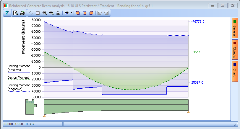
Click on the Analyse for drop down and select “Shear for gr1b-gr5 1” from the list. The plot of results will now show the design shear together with the maximum allowable shear force and the shear force resistance with nominal links.
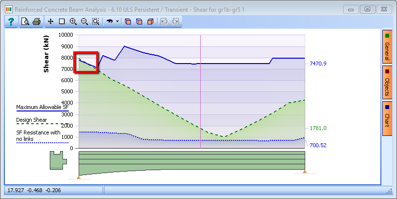
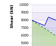
It can be seen that the design shear is slightly greater than the max allowable shear at the left hand support.
To increase the max allowable shear the strength of the concrete could be increased but more conveniently the angle of the compression strut in the concrete could be increased for the shear calculations. The effect of this will increase the shear link reinforcement requirements while reducing the amount of longitudinal shear reinforcement required. Only a small adjustment is required.
-
In the Set Parameters for data field select “Shear Calculations” to display the Design Data for Shear data form. Change the Angle between strut and beam axis from “21.80141” (the default and the minimum) to “22.5” degrees.
-
Close the form with the ✓ OK button.
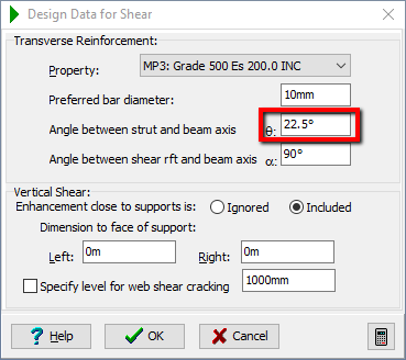
The default bar diameter is set to 10mm, which is what will be used in the calculation of the link spacings. This can be changed in this form if required.
-
Click on the Results button to view the shear calculations. Scroll down to the bottom of the results to see summary of link requirements.
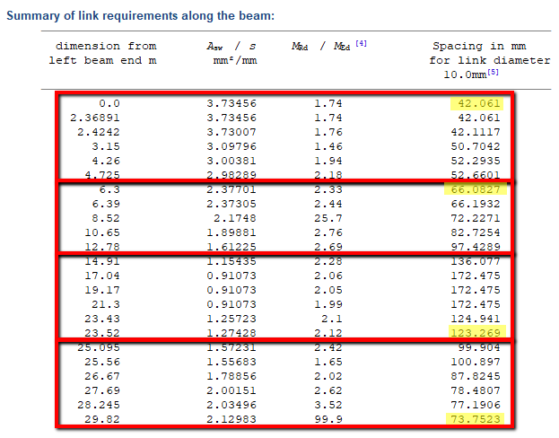
Looking at the results, it can be seen that the link spacings may be put into four groups. These are:
- 0m to 6m
- 6m to 15m
- 15m to 25m
- 25m to 29.82m
Based upon the table above it is suggested to use:
| Location | Diameter | Legs | Spacing |
|---|---|---|---|
| 0m to 6m | 10mm | 6 | 125mm |
| 6m to15m | 10mm | 6 | 200mm |
| 115m to 25m | 10mm | 4 | 250mm |
| 25m to 29.82m | 10mm | 4 | 150mm |
-
Close the Results Viewer with the “Exit” button at the top of the viewer.
Design for SLS
The beam also needs to be checked at Serviceability.
-
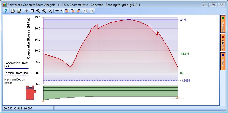
In the Reinforced Concrete Beam Analysis form click on the Analyse for drop down and select “Bending for gr1b-gr5 1” from the list.
-
Make sure the Limit State option is set to “SLS Characteristic”.
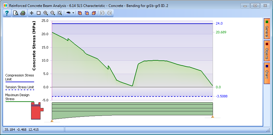
The graphical results show the design stress line is now red because the beam design does not quite pass for the sagging case by a small margin. The user may want to consider whether to make further adjustments to such a beam. Repeating this for the hogging case shows that the beam still passes for hogging.
Finally, the strength of the concrete beam, at say, 14 days can be checked in accordance with clause 3.1.2 of EN 1992-1-1. (Assuming cement strength of Class R).
-
Click ✓ OK to close the Reinforced Concrete Beam Analysis form then change the navigation window to Materials.
-
Select the grade C40/50 concrete material to open the Define Property Details form and then change _Characteristic Strength, fck to 36.85MPa.
-
Click ✓ OK to close the form.
-
Change the navigation window to Design Beam and click on the
Analyse toolbar button to open the Reinforced Concrete Beam Analysis form. -
Set the Analyse for field to “Construction stage” and set the Limit State field to “6.10 ULS Persistent/Transient”. It can be seen that the beam still passes for construction stages at ULS.
-
Set the Limit State option to “SLS Characteristic” to confirm that it also passes. When the analysis form is open the results graphs can be displayed in a 3D isometric window by clicking on the
 3D view icon on the graphics window:
-
Click ✓ OK to close the Reinforced Concrete Beam Analysis form then click on the File | Save As... menu item.
-
Set the file name to “My EU Example 5_3.sam” and click on the “Save” button.
-
Close the program.
Summary
In this example we have changed the length of a standard beam to fit a specific structure then carried out a detailed design. During the design process we have modified the reinforcement by adding, removing and curtailing bars. We have also checked the design with a reduced concrete strength at 14 days in accordance with clause 3.1.2 of EN 1992-1-1.