Create the Model JSON
JSON is a flexible format that allows you to write code for reading and writing data in various programming languages. ASBD software provides examples written in C# that demonstrate how to work with the available model data. You can refer to the Coding Sample topic for more information on using these examples.
Creating a JSON file can be done programmatically or manually using an online editor. If you choose to create it manually, it is often easier to start with a similar existing file and modify it to meet your specific requirements. Additionally, any existing SAM or SST file can be saved as JSON, as the software supports reading and writing JSON in addition to the binary format.
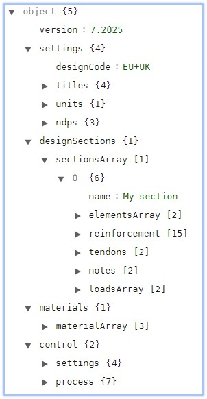
Here is a JSON example, showing the higher-level objects.

It contains 5 main blocks.
settingsThis object contains parameters relating to the Design Code, Titles, Units, and for Eurocodes only, the Nationally Determined Parameters.designSectionsThis object contains parameters relating to one or more Design Sections.designBeamsThis object contains parameters relating to one or more Design Beams.materialsThis object contains parameters relating to the material definitions (concrete, steel, reinforcement, prestress, etc.).controlThis object controls automation and will be discussed below.
The example above defines a single section made up of 2 elements. There is a block which details the reinforcement and tendon location, an optional notes object and an array containing 2 load cases.
Design Sections or Beam sections can be made up of parametric shapes; user defined elements of any shape defining the perimeter which can include arcs; or can be from standard concrete or steel libraries. Here are some examples of these different types.
Parametric Shape
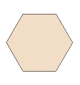
Simple Hexagon Polygon Definition

{
  "shape": "6_BASE",
  "side": 0.5,
  "hookref": 0,
  "hookY": 0,
  "hookZ": 0,
  "propertyRef": "MP1"
}
Simple Rectangle Definition
{
  "shape": "RECTANGLE",
  "width": 0.8,
  "depth": 0.95,
  "hookref": 0,
  "hookY": 0,
  "hookZ": 0,
  "propertyRef": "MP1"
}
User Defined Shape
Precast Section with Curved Sides

{
  "type": "PRECAST",
  "originType": "USER",
  "perimeter": {
    "nodes": [
      0.35,
      0,
      0.375,
      0.025,
      0.37,
      0.202,
      0.1533,
      0.3441,
      0.1169,
      0.3866,
      0.1091,
      0.442,
      0.2255072463768116,
      1.245,
      0.2205072463768116,
      1.25,
      0.1855072463768116,
      1.25,
      0.1855072463768116,
      1.3,
      -0.1855072463768116,
      1.3,
      -0.1855072463768116,
      1.25,
      -0.2205072463768116,
      1.25,
      -0.2255072463768116,
      1.245,
      -0.1091,
      0.442,
      -0.1169,
      0.3866,
      -0.1533,
      0.3441,
      -0.37,
      0.202,
      -0.375,
      0.025,
      -0.35,
      0
    ],
    "arcs": [
      5,
      16
    ]
  },
  "propertyRef": "MP2",
  "name": "Y7 Beam",
  "precastAge": 4
}
Standard Libraries
Standard concrete or steel components in ASBD are referenced by their identifiers. The list of identifiers can be found in the default installation location:
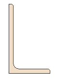
C:\Program Files\Autodesk\Structural Bridge Design 2025\Schema To define a specific component, such as a European unequal angle 150 x 90 x 10, you can refer to the document "EuropeanSectionsSteel.pdf" to find the corresponding identifier (id) for that particular component.


The JSON to describe this shape is:
{
  "shape" : "STANDARD_STEEL",
  "id": 30311007,
  "hookRef": 1,
  "hookY": 0,
  "hookZ": 0,
  "propertyRef": "MP1"
}
In this JSON structure, the shape field indicates that it is a standard steel component. The id field represents the identifier for the specific shape, which in this case is 30311007. The hookRef, hookY, and hookZ fields define the hook reference and its Y and Z coordinates, respectively. The propertyRef field refers to the material property identifier, which in this case is MP1.