Post-tensioned Beam Tendon Definition
Description
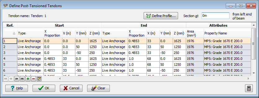
This form defines all the tendons used for prestressing the beam, and may be accessed either from the Post_tensioned beam definition form, or directly from the Post_tensioned beam calculations form (by clicking on the beam elevation in the graphics window).
Each row of the table in this form corresponds to a single tendon and defines the 'Reference Axis' (the straight line connecting the start and end coordinates specified) and shows the attributes (name and area) of that tendon.
Tendons are added by clicking the mouse on the + (Insert Tendon) button. This brings up the Define Tendon Locations form by which the positions and areas of one or more tendons may be specified. They are automatically added to this form.
Tendons are removed by highlighting one or more rows of the table (using mouse click or SHFT-Click or CTRL-Click on rows in the table or, alternatively, by boxing around the group in the graphics window by clicking with the mouse at one corner of the box, and then clicking again at the opposite corner) and then clicking on the - (Remove Tendon) button. The highlighted rows are deleted.
Tendon attributes (strand, duct, material type, anchorage type and anchorage position) are edited in the Edit Tendon Attributes form accessed by highlighting one or more rows and then clicking on the Edit Tendon Attributes button in the navigation toolbar at the bottom of the table. The highlighted rows are edited.
Tendon profiles are defined in the Define Post_tensioned Tendon Profile form accessed by highlighting one or more rows and then clicking the mouse on the Define Profile button. The reference axis already defined becomes the default in the Define Post_tensioned Tendon Profile form.
The flagged cross-section (out)line in the graphic window may be re-located by editing the 'Section at' field or, alternatively, by drag and drop with the cursor. The cross-section in the graphic window is updated as the line is moved to show the tendons at its current location.
Mouse Control
The set of highlighted tendons may be selected from within the graphics window by:
- Clicking the mouse with the cursor over a tendon (in section or elevation) to highlight a single tendon.
- Holding the <CTRL> (Control) button on the keyboard down whilst clicking with the mouse over several successive tendons (in section or elevation) to highlight several tendons.
- Clicking the mouse with the cursor in the section and then moving the cursor to box around one or more tendons before clicking again to highlight the boxed tendons.
The flagged cross-section (out)line in the graphic window may be re-located by editing the 'Section at' field or, alternatively, by placing the cursor over the outline (to highlight it red) and then holding the mouse button down whilst moving the cursor to drag it to a new position where the mouse button is released (drag and drop). The cross-section in the graphic window is updated as the line is moved to show the tendons at its current location.
Form Graphic
Field Help
Define Profile
This option is used to fully define the tendons profile, stressing data, and prestress loss parameters.
Section at
This field indicates the location along the elevation at which the cross section of the beam is drawn. The location is also indicated on the elevation by a flagged (out-)line. To draw a different section, either enter the location in this field, or use the mouse to move the section to the required location on the elevation.
Type
This column of the table defines both the type of tendon, and the type of the anchorage at either the start or end of the tendon according to the column group header. The tendon type may be either:
- Internal (bonded)
- External
- Pretensioned
The anchorage type may be either:
- Live (i.e. stressed from this end)
- Dead (i.e. not stressed from this end)
The program will not allow incompatible selections (e.g. dead anchorage at both ends, or a combination of internal and external in the same tendon). A prestressed tendon will only be allowed in a section of concrete that is defined as Precast. If pre-stressed type is selected, the tendon will be set to straight along its full length.
X Proportion
The location of the anchorages along the length of the beam may be specified as a proportion of the full length in this field, or as a dimension from the start (left end) of the beam in the next field.
X / Y / Z
The coordinates defined here for the start and end of the tendon define the tendon's 'Reference Axis'. The reference axis is used for setting out the tendon profile for tendons that are not straight for their full length. The reference axis is also the tendon's default profile. When the tendon location is defined, the reference axis coincides with the defined location coordinates, and extends the full length of the beam.
The X origin is defined by the start (left) end of the beam. The Y/Z origin is defined in the definition of the section geometry.
Area
The area of each tendon is displayed in this column. The area may not be edited here. To edit the area, highlight the appropriate rows and then click on the 'Edit tendon attributes' in the 'navigation toolbar' at the bottom of the table.
Property Name
The material property for each tendon is displayed in this column. The material property may not be edited here. To edit the material property, highlight the appropriate rows and then click on the 'Edit tendon attributes' in the 'navigation toolbar' at the bottom of the table.
Edit Tendon Attributes
The options available for this control (located in the 'Navigation toolbar' at the bottom of the table are more fully described in the Form Help.
The attributes which may be altered are:
- strand area and number of strands in the bundle
- duct diameter, and offset of the tendon within the duct
- material property
- anchorage type at the start (left) and end (right) ends of the tendon
- location along the beam at which the tendon starts and ends
Highlight the appropriate rows and then click on this control.