Generate from Applied Trapezoidal Loads
Description
This form enables the bending moments and shear forces along a beam to be generated from a trapezoidal distributed load along the beam, or part of the length of the beam, using simple beam theory. An allowance for rotational restraint at the ends of the beam may be made by including some redistribution of load from the supports.
Relatively complex load patterns may be built up from a series of individual load components. The Add Load Component button or the Insert key can be used to add additional loads. The Remove Load Component or Delete key removes previously defined components. When the OK button is clicked the sum of load components will replace any existing loads on the beam.
Note that the load effects calculated here make no allowance for varying stiffness (EI) along the beam.
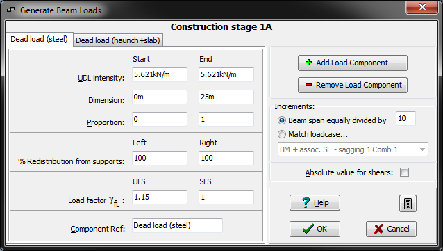
Form Graphic (for steel composite beams)
Field Help
UDL intensity
Enter the intensity of the Trapezoidal Distributed Load at the left hand end and right hand end of the loaded length. The values must be entered as load intensity per unit length of the beam. The nominal load should be entered here, and load factors may be entered for ULS and SLS in the appropriate fields below.
Negative values of load intensity cannot be entered here, but a negative load may be obtained by setting the load factor to a negative value.
Dimension
Proportion
The Trapezoidal Distributed Load may be applied over a portion of the span only. Enter the start and end dimensions.
The position along the span can be specified either as a dimension from the left hand end, or as a proportion of the total distance from the same end. The two values are inter-related in the program, and an entry of either one will cause the other to be calculated and displayed automatically.
% Redistribution from supports
If a value is entered for redistribution from supports, the moment at the support is reduced by the percentage specified. The moments along the span are increased by a corresponding amount. The shear forces are adjusted to restore the static equilibrium of the beam.
100% redistribution is equivalent to replacing an encastre support with a simple support. In this way it is possible for example to enter the construction stage loading for a beam which is simply supported for initial dead loads.
Load factor γfL Enter the load factors (γfL for steel composite beams, or γfL.γf3 for prestressed beams) by which the load arising from the trapezoidal load specified above will be multiplied to give the design load effects.
A negative value may be used to reverse the sign of the loading.
Component Ref
A component title can be entered here for easy identification
Beam span equally divided by
Match Loadcase
The load effects generated from the trapezoidal load components specified on this form are transferred as loading data at increments along the beam which are defined here. The options are:
Beam span equally divided:
In this case the span of the beam is divided by the value specified on the field, to give a value of the increments along the beam at which the load effects are generated.
Match Loadcase:
In this case, if increments have already been defined for the current load case prior to entering this screen, those locations will be used. Alternatively if increments have already been defined for another load case prior to entering this screen, those locations may be used by selecting the loadcase from the drop-down list.
Absolute value for shears
If this box is checked all the shear values will be generated as positive.