Automated Loadings - Live Load Envelope for LRFD
Description
The Live Load Envelope page of the Automated Loadings form is used to generate envelopes of moments and shears for the HL-93 loading described in Article 3.6.1.2 of AASHTO LRFD. It operates by creating influence lines for a series of points along the beam. It then uses the influence lines to place the lane load and vehicle loads at the positions which maximize the effect at each influence point. The points at which the influence lines are created are determined by the number of divisions along the beam which was specified when the structure geometry data was entered.
Outline Procedure
This form is accessed from Define | Automate Live Loads.
First check the 'Included' boxes to select all the vehicles that are to be included. For example if the double design tandem is not to be included, leave that box clear. Right clicking over the 'included' list displays a shortcut menu to facilitate selection. If any permit or convoy vehicles have been defined then boxes for these will also be available.
The results are envelopes of effects. For instance, selecting 'Design Truck' alone will give the most extreme moments, shears and reactions that are caused by the design truck acting along with lane load. If 'Design Truck' and 'Double Design Truck' are selected then in some locations (normally negative moment and reactions at interior supports) the double design truck will cause greater effects than the design truck and so its effects are used for the envelope of results in these locations.
The critical vehicle position for each influence line is determined by the program by positioning the vehicle initially with its front axle just on the left end of the beam, and moving the vehicle step by step along the beam, calculating its effect at each step, and remembering the position which causes the worst effect. The distance by which each vehicle is moved along the beam with each step is specified as the 'Increment'.
When the data on the form has been set up as required click onto the Analyze button. The program will then calculate all the required influence lines. When this analysis has completed the program will run the vehicles across the beam as required to determine the envelopes for moment and shear, which will be displayed as soon as the calculations are complete.
The field in the 'Display Options' region will contain one or more of the following, depending on which vehicles have been included:
- Envelope for Strength I and Service
- Envelope for Strength II
- Envelope for Fatigue
- Influence Line for Moment
- Influence Line for Shear
Select one of these options to display the appropriate moment and shear envelopes, or influence line.
For the envelope results, the two green lines correspond to the maximum positive and negative moment envelopes. The solid red line corresponds to the maximum shear envelope.
Click on the Results button to see the values at each point along the beam for the currently displayed plot. Envelope results will include the vehicle and its position, and direction (together with the axle spacing or vehicle spacing if relevant) which caused that critical effect. The results also show the lane loading (UDL) that accompanies the vehicle loading.
The moment and shear envelopes may be transferred directly to the design beam for design and code checking of the beam by clicking on the Transfer Results button, and selecting the beam that is to be designed.
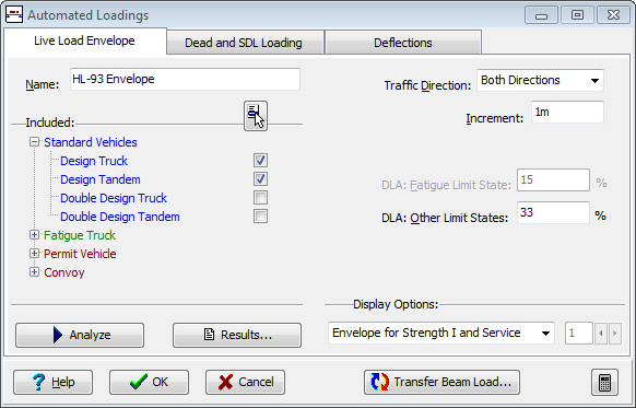
Form Graphic
Field Help
Name
The name will appear for example in the 'Results' printout.
The default name of HL-93 Envelope' may be changed if required by entering an alternative name in this field.
Included Vehicles
Check the boxes for all the vehicle types that may be included in the calculations to determine the worst effect. If permit vehicles or convoys have been defined, then boxes for these will be available for selection. Strength II envelopes will only be calculated if one or more permit vehicles or convoys are included.
Selecting only double design truck or double design tandem will calculate results only for those conditions (negative moment and reactions at interior supports) where the individual vehicles cause maximum force effect when placed in adjacent spans for which these vehicles are explicitly defined in Article 3.6.1.3.1 of AASHTO LRFD. For the double design truck (only) the total effect of the vehicle and lane load will be factored by 90%.
Lane loading will always form part of the calculated loads (except for the fatigue vehicle). Deflections will only be calculated if the design truck is selected (as defined in Article 3.6.1.3.2 of AASHTO LRFD).
Right clicking over the list displays a shortcut menu to facilitate selection.
Traffic Direction
Vehicles whose axle loads or positions are not the same in the forwards and reverse direction cause different effects in each direction. This field is used to determine whether the vehicles are to be moved left to right only, right to left only or in both directions to determine the worst effects. This field is enabled only when a non-symmetric vehicle is selected.
Increment
The critical vehicle position for each influence line is determined by the program by positioning the vehicle initially with its front axle just on the left end of the beam, and moving the vehicle step by step along the beam, calculating its effect at each step, and remembering the position which causes the worst effect. The maximum distance by which each vehicle is moved along the beam with each step is specified as the 'Increment'.
The 'Increment' also defines the maximum amount by which the variable space between the two main axles of the design truck is changed between its shortest and longest values. It also defines the maximum change in spacing between trucks for the double design truck, and between tandems for the double design tandem. It also defines the maximum length of segments of lane loading to be applied (or not if they are relieving). It also defines the maximum amount by which the variable space defined in some permit vehicles is to be altered.
An initial 'Increment' is calculated by the analysis process; based on structure parameters and segment length. The 'Increment' actually applied is the smaller of the initial value and the value entered in this 'Increment' field. So calculation is unlikely to be made faster by entering a large value in this field; but may be slowed by a smaller entry. Whatever the setting of this 'Increment' field, all loadings are 'converged' to the extent that their net effects should be within 1% of the theoretical maximum possible for the influence line.
The default value for this field will generally suffice.
DLA: Fatigue Limit State
The Dynamic Load Allowance specified in this field will be applied to the fatigue vehicle. This field is only editable if the fatigue vehicle is included. The default value of 0.15 is obtained from Table 3.6.2.1-1 of AASHTO LRFD.
DLA: Other Limit States
The Dynamic Load Allowance specified in this field will be applied to all vehicle loadings (not lane loadings) except the fatigue vehicle. This field is only editable if a vehicle other than the fatigue vehicle is included. The default value of 0.33 is obtained from Table 3.6.2.1-1 of AASHTO LRFD.
Display Options
The graphical display depends upon the selection made in this field.
The 'Envelope for Strength I & Service' option will only be available if design truck or design tandem vehicles have been included in the analysis. 'Envelope for Strength II' will only be available if permit or convoy vehicles have been defined and included in the analysis. 'Envelope for Fatigue' will only be available if the fatigue vehicle has been included in the analysis.
If the display option selected is an influence line, the adjacent field will be available to select the location along the beam for the particular influence line.