3.1 General Section Properties
Subjects Covered
- Gross section properties
- Transformed section properties
- Net Transformed section properties
- Full plastic moments; Moving the section origin
- Reinforcement bar translation.
- Results viewer
- PDF results viewer
Outline
The calculation of section properties for three of the sections defined in section 2 will be considered as follows:
| Example 2.6 | Calculate |
|---|---|
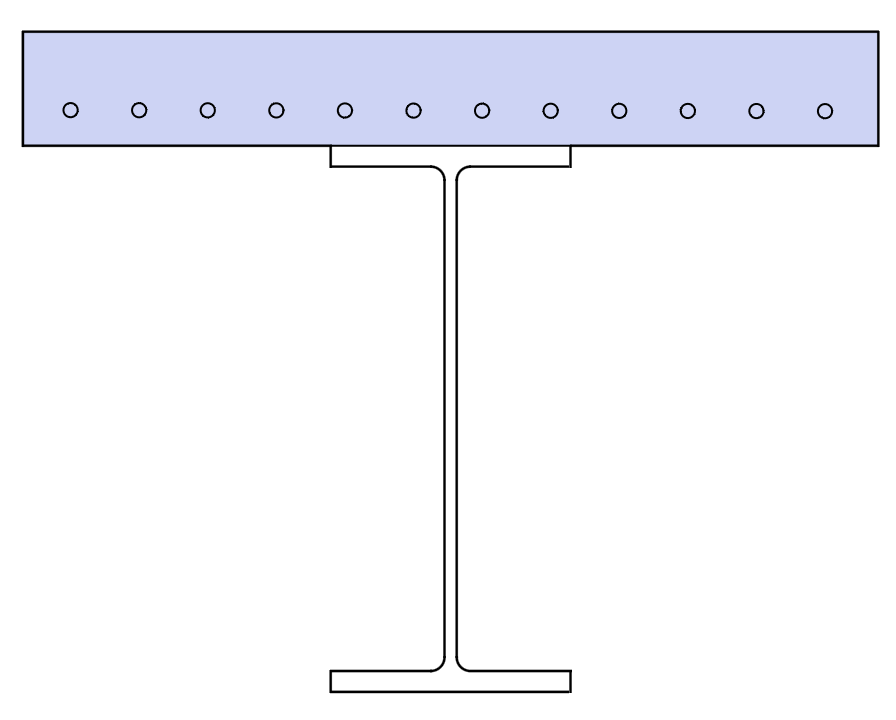 |
Section properties of the gross section (neglecting any difference between material properties). Section Properties of the transformed section (transformed to grade C32/40 concrete). Transformed bending Inertia Ixx about an axis 200mm below the bottom of the slab (the global centroid axis of the complete bridge deck cross section). |
| Example 2.2 | Calculate |
|---|---|
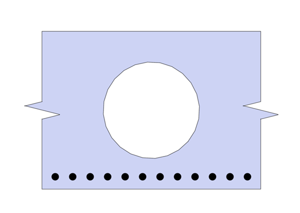 |
Net transformed Ixx (cracked section properties) transformed to grade C32/40 concrete. |
| Example 2.4 | Calculate |
|---|---|
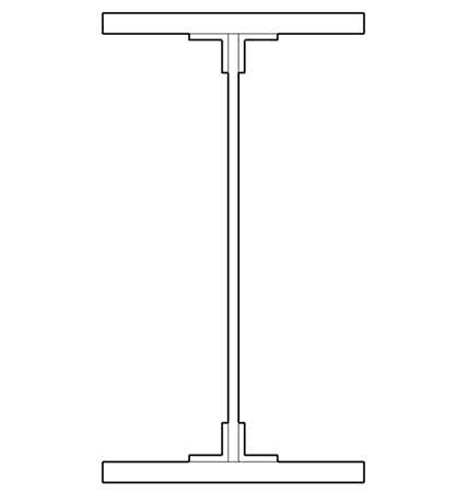 |
Full plastic moment of the section according to EN1993-1. |
Procedure
-
Start the program and use the menu item File | Open to open the file “My EU Example 2_6.sam” created in example 2.6.
-
Use the menu item File | Titles to open the Titles form. Change the Sub-title to “Example 3.1a and the Job Number to “3.1a”. Click on ✓ OK to close the Titles form.
-
In the Design Section navigation window right mouse click and choose Analyse Section | Section Properties which will open the data form for section property calculations (this is also reached from the navigation window toolbar as shown).
Gross Section Properties
-
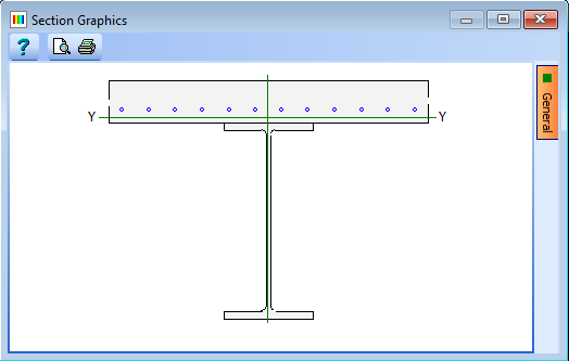
Click on the Section properties for drop down and select “Gross Section” from the list. This will display the results shown below.
-
Click on the Results... button to see the detailed results as a text file. This can be saved as a Rich Text Format (rtf) file if required.
-
Click on the “PDF View” tab at the bottom of the results viewer to display the results with the graphics in the form of a PDF document. This can then be saved as a PDF file if required. Page numbering, User defined titles and margins can be configured using the Preferences button at the top of the viewer.
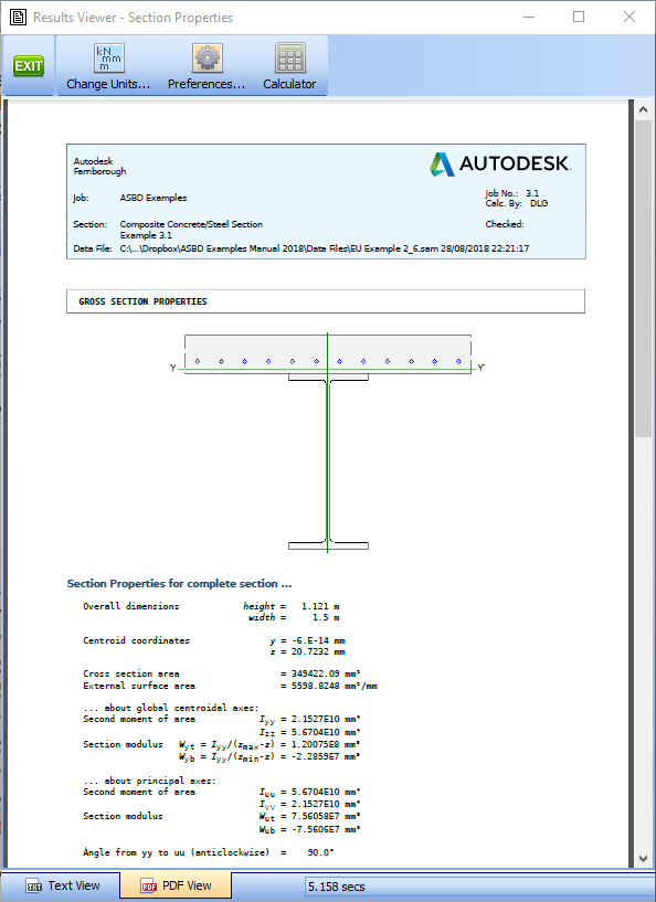
-
Close the Results Viewer using the green EXIT button at the top.
Transformed Section Properties
-
Click on the Section properties for drop down and select “Transformed section." This will display the results shown below.
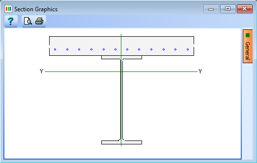
-
Click on the Results button to see the detailed results.
-
Close the results viewer.
-
Click ✓ OK to close the Calculate Section Properties form.
Section Properties about a specified axis
For properties about a specific axis we need to define the origin of the section at the level of the required axis. One set of properties calculated are about the global axes.
-
In the Design Section navigation window select the “Slab” element and set the z coordinate of the hook point to 200mm. Click ✓ OK to save this change.
-
Repeat this for the Steel element.
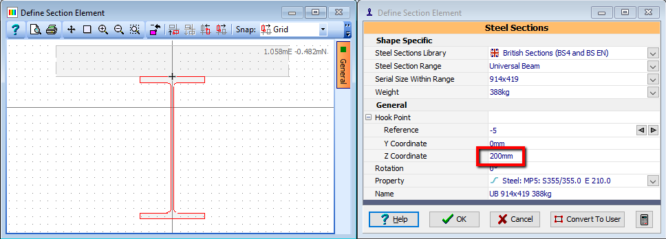
-
Select the "Reinforcement" item in the navigation window.
-
Click on the Edit bars... button.
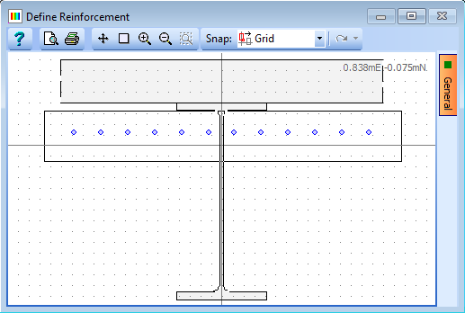
-
Click once on the graphics window to the bottom left of the section, then move the mouse until the selection box contains all the bars. Click again to select the bars which will be highlighted in red. The Edit Reinforcement form will open.
-
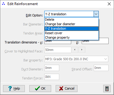
Click on the Edit Option drop down menu and select Y-Z Translation.
-
Change the value in the Translation dimensions – z field to “200."
-
Click ✓ OK to move the tendons and close the Edit Reinforcement form.
-
Click ✓ OK to close the Define Bars and Tendons form with the changes.
-
Analyse the section by clicking on the
 dropdown in the navigation window toolbar and selecting “Section Properties."
 -
Click on the Section properties for drop down and select “Transformed section”. This will display the results shown below.

-
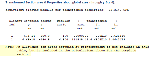
Click on the Results button to see the detailed results and scroll down the page until the table for Transformed Section area & Properties about global axes (through y=0,z=0): is shown:
-
Close the results viewer.
-
Click ✓ OK to close the Calculate Section Properties form.
-
Use the File | Save As... menu to open the Save As form.
-
Change the filename to “My EU Example3_1a.sam” And click on the “Save” button.
Net Transformed Section Properties
-
Use the menu item File | Open to open the file “EU Example 2_2.sam” created in example 2.2.
-
Use the menu item File | Titles to open the Titles form. Change the Sub-title to “Example 3.1b” and the Job Number to “3.1b”. Click ✓ OK to close the Titles form.
-
From the navigation window select the
 toolbar button dropdown arrow and select Section Properties which will open the section properties form.
 -
Click on the Section properties for drop down list and select “Transformed Section."
-
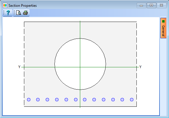
Click on the Transformed to drop down list and select “MP1: C32/40 Ecm 33.3”. This will display the results shown below.
-
Click ✓ OK to close the Calculate Section Properties form.
-
Use the File | Save As... menu to open the Save As form.
-
Change the filename to “My EU Example 3_1b.sam” And click on the “Save” button.
Plastic Section Properties
-
Use the menu item File | Open to open the file “EU Example 2_4.sam” created in example 2.4.
-
Open the Design Section navigation window and use the
 toolbar button to select the dropdown arrow and then select Section Properties which will open the section properties form.
 -
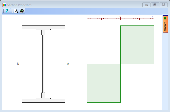
Click on the Section properties for drop down list and select “Plastic Section”. Also set the Transformed to field to the Structural Steel material. The form will now display the results shown below.
-
Click on the Results button to see the detailed results for the Plastic Modulus of the Section.
The top of the results file is shown below.
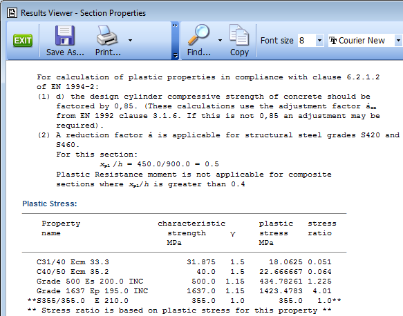 Note: The notes at the top of the results output are related to EN1994 for composite sections, therefore they do not apply to this steel only section. The reason that this is present is because there are concrete materials defined in the material properties.
 -
Close the results viewer and the analysis form and then use the Materials navigation window task to clear unassigned materials. This should leave just the steel material.
-
Now, re-analyze the section for plastic section properties, note that the plastic resistance moment is the same and then open the results viewer again. This time the notes regarding EN 1994 are not present.
Note: However, as this is a steel-only section we need to comply with clause 5.5 of EN1993-1. Assuming that the height of the web and the width of the flange are measured from the edge of the cleat, this section is class 1 so we can therefore use these properties for a global plastic analysis according to clause 5.6 (2) of EN1993-1. -
Close the results viewer and the Calculate Section Properties form by clicking the ✓ OK button.
-
Use the File | Save As... menu to open the Save As data form and save the data as “My EU Example 3_1c.sam”.
-
Close the program.
Summary
The calculation of section properties is very easy, but very powerful as gross, transformed and cracked section properties can be obtained. The choice of which property to use will depend on the type of analysis to be performed using these properties.
Reinforced concrete sections for Ultimate Limit State calculations will generally use gross properties whereas Composite steel and Prestressed concrete sections will normally be transformed. Net transformed properties (cracked) are most useful when considering the deflections of a reinforced concrete structure.
Fully Plastic Moments and Modulus of a steel section are useful as input to a plastic hinge analysis of a structure and would be applied as “Member Limits” to an Autodesk® Structural Bridge Design structural analysis.