3.8 Staged Construction Of A Composite Section
Subjects Covered
- Section Stages
- Saving Intermediate Files
- Initial Strains
- General Stress/Strain Analysis
Outline
A 30m long composite beam is constructed in two stages.
- The steel beam supports its own weight plus the weight of the wet concrete (24kN/m³ density of concrete – 77kN/m³ density of steel).
- The beam becomes composite and supports an additional mid-span design moment of 1500kNm due to surfacing. Determine the as-built stresses due to this loading.
Use the composite section saved in the General stress strain example. Determine the areas of both beam and slab so that the dead load mid-span moments can be determined. Delete the slab and reinforcement element from the section and apply the dead load moment. Carry out a general stress strain analysis to determine the strains in the steel beam. Add back the slab and reinforcement elements and apply the strains from the first analysis as initial strains. An additional bending moment of 1500kNm is then applied before carrying out a second general stress strain analysis of the whole section to determine the stresses.
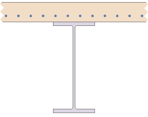
As this analysis requires two section, one for the steel beam only and the other the composite section, we will carry this out in multi-section project so all data is available in one file rather than two.
Procedure
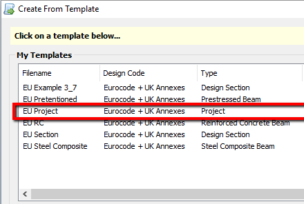
- Start the program and use the menu item File | New | Create from template... and then double clicking on “EU Project”. This will create a new project with pre-defined materials that were defined in section 1 of the manual.
| File Menu | EU Project |
|---|---|
 |
 |
-
Use the menu item File | Titles to input the Project Title as “Composite Section Staged Construction”, the Sub-title to “Example 3.8” and the Job Number to “3.8”. Click on ✓ OK to close the Titles form.
-
In the Design Sections navigation window click on the
 toolbar button and select “Existing Design Section” which will allow you to select the file “EU Example 3_6.sam” which was created in section 3.6 of this manual. This creates a linked section – which we cannot edit directly - so we need to change it to an embedded section by right clicking on it in the navigation window and selecting “Break Link”.
 -
The existing loadcase needs to be deleted so select it in the navigation window and then use the “-“ toolbar button to delete it (and close any other forms that may pop up).
-
Copy this section in its entirety by selecting the section “SS1” in the navigation window, right mouse clicking and selecting “copy” from the resulting context menu.
-
Rename “SS1” section to “Stage 1 Section” and “SS2” section to “Stage 2 Section”. This is done by selecting each of the sections in turn and then the right mouse click will allow the option to rename.
-
Remove the reinforcement for Stage 1 section by selecting “Reinforcement” in the navigation tree for this section, which will display the Define Reinforcement form. The Clear button will remove all reinforcement before closing the form with the ✓ OK button.
-
Remove the “Rectangle” element for stage 1 section by selecting it in the navigation tree and deleting it with the “-” button in the navigation toolbar. Close any other forms that may be open
Determine and Define Dead Loads
-
With “SS2: Stage 2 Section” selected, find the cross-sectional area of the beam, use the
 toolbar button dropdown to select “Section Properties” which will open the Section Properties form.
 -
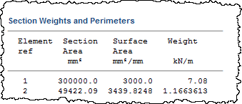
Click on the Results button to open the Results Viewer. The area of the slab is 0.3m2. The area of the beam is 0.04942m².
-
Close the Results Viewer and click on the ✓ OK button to close the Section Properties form.
-
The dead load moment to be applied for the concrete slab is 810kNm (0.3×24×302/8). The dead load moment to be applied for the steel beam is 428.1kNm (0.04942×77×302/8). These should both be applied to Stage 1 Section.
-
With “SS1: Stage 1 Section” selected in the navigation window, create a new loadcase for this section by clicking on the
 toolbar button at the top of the navigation window and selecting “Loadcase...”. This will open the Define Loadcase form.
 -
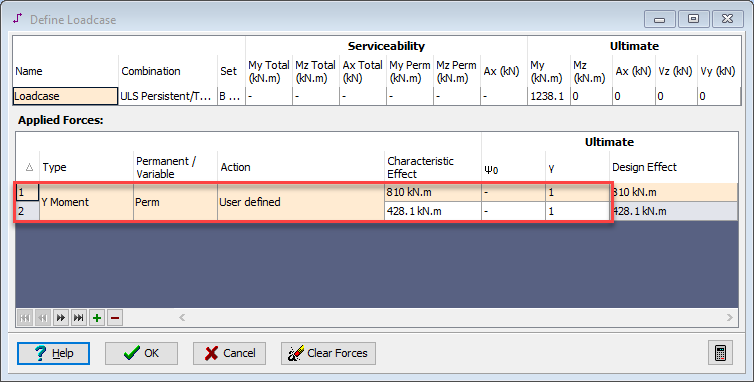
Create 2 new components to this load case by clicking twice in the “+” button at the bottom of the table.
-
In the first row of the table, click the Type column and select “Y Moment” from the drop down list.
-
Enter a value of “810kNm” in the Characteristic Effect field.
-
On the second row of the table, click in the Type column and select “Y Moment” from the drop down list.
-
Enter a value of “428.1kNm” in the Characteristic Effect field.
-
Select “Perm” from the Perm/Variable drop down list in both rows.
-
Select “User defined” in the Action column on both rows.
-
Change the Ultimate γ factors to 1 by entering “1.00” in the relevant fields and pressing ‘Enter’ on the keyboard.
-
Click on the ✓ OK button to close the Define Loads form.
Determine Strains on Steel Beam
-
With “SS1: Stage 1 Section” selected, right mouse click and select “Tolerances”.
-
Change the tolerance for the three effect components from “2.0” to “0.1” before closing the form with ✓ OK.
-
Then use the
 toolbar button dropdown to select “General Stress Strain” which will open the General Stress / Strain form.
 -
Ensure that Loadcase: is set to “SL1: Loadcase” and Resistance: is set to “Not Used”.
-
Click on the “Results” button to open the Results Viewer.
-
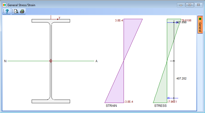
The maximum and minimum strains in the beam are 0.00037849 and -0.00037849 respectively.
-
Close the Results Viewer and click on the ✓ OK button to close the General Stress Strain form.
Apply Stage 1 Strains as Initial Strains in Stage 2
-
In the navigation window select “Initial Strains” for section “SS2: Stage 2 Section” to open the Define Initial Strains data form.
-
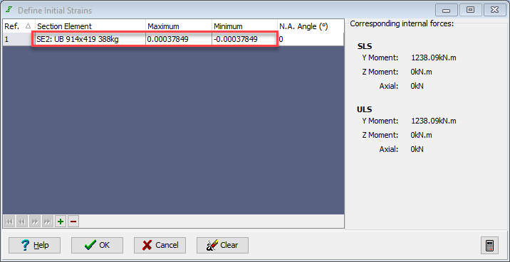
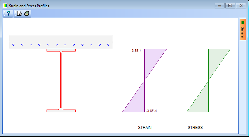
Click the “+” button at the bottom of the form to create an entry. The Steel beam should be chosen from the drop down in the Section Element field and the Maximum field set to “0.00037849” and the Minimum field set to “-0.00037849”. If the “Enter” key is pressed the graphics displays the applied strains and resultant stresses.
| Define Initial Strains | Strain and Stress Profiles |
|---|---|
 |
 |
-
Click the ✓ OK button to close the Define Initial Strains form.
Apply Moment Due To Surfacing
-
Select the loadcase already defined for stage 1 in the navigation window which will open the Define Loadcases form.
-
Right mouse click in the applied forces table and select “Copy Table to Clipboard”.
-
Close the form with the ✓ OK button.
-
With “SS2: Stage 2 Section” selected in the navigation window, create a new loadcase for this section by clicking on the
 toolbar button at the top of the navigation window and selecting “Loadcase." This will open the Define Loadcase form.
 -
Right mouse click in the Applied Forces Table and select “Paste From Clipboard (Replace), which will add two rows to the load table.
-
In both of these rows re-set the Gamma factor to “1.0”.
-
Click the “Insert Record” button near the bottom of the form to add a third row to the table.
-
In the third row of the table, click in the Type column and select “Y Moment” from the drop down list.
-
Enter a value of “1500kNm” in the Characteristic Effect field.
-
Select “Perm” from the Perm/Variable drop down list.
-
Select “User defined” in the Action column on the third row.
-
Change the Gamma values to 1 by entering “1.00” in the relevant fields.
-
Click on the ✓ OK button to close the Define Loads form.
Calculate Final Stresses/Strains
-
Use the
 toolbar button dropdown to select “General Stress Strain” which will open the General Stress / Strain form. Ensure that the Loadcase: is set to “SL1”and Resistance: is set to “Not Used”.
-
Click on the Results button to open the Results Viewer.
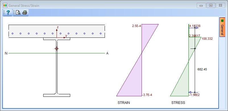
- The maximum and minimum stresses for the concrete slab are 4.18N/mm² and 2.40N/mm² respectively.
- The maximum and minimum stresses for the steel beam are 108.33N/mm² and -156.49N/mm² respectively.
-
Close the Results Viewer and click on the ✓ OK button to close the General Stress/Strain form.
-
Save the data file as “My EU Example 3_8.sam” by using the menu item File | Save As...
Compare with Non-Staged Construction Analysis
-
To compare the as-built stresses to those that result from applying the load cases in one go to the whole section we can re-analyse the SS2: Stage 2 Section with the initial strains removed.
-
Select the “Initial Strains” item in the navigation tree for the Stage 2 section.
-
Click on the “Clear” button to remove the initial strains.
-
Click the “Yes” button in the confirmation box that appears.
-
Click the ✓ OK button to close the Define Initial Strains form.
-
Re-Analyse this section for general stress strain and click on the “Results” button to open the Results Viewer. The tables below show the comparative stresses:
Stress Comparison Table for Defined Grade C32/40 Concrete
| In Stages | Composite | |
|---|---|---|
| Max Stress | 4.18 N/mm² | 7.37 N/mm² |
| Min Stress | 2.40 N/mm² | 4.375 N/mm² |
Stress Comparison Table for Defined Structural Steel
| In Stages | Composite | |
|---|---|---|
| Max Stress | 108.33 N/mm² | 55.06 N/mm² |
| Min Stress | -156.49 N/mm² | -141.5 N/mm² |
- Close the Results Viewer and click on the ✓ OK button to close the General Stress Strain form.
- Close the program without re-saving the data file.
Summary
A staged construction must be carried out as two or more separate analyses. The first analysis considers the first stage section components only and a load applied to represent the total load at this stage. From this analysis the max & min strains of the first stage components can be determined.
The second analysis includes stage 1 and stage 2 section components and the full load at this stage applied. Stresses and strains at this stage are then available.
If required, the strains at this stage can be used as input to further stages.
Also note that the strains shown on the graphic are the additional strains due to the additional load – not the total strains – these are shown in the text results. The stresses on the graphics are the total stresses but can also be obtained from the printed results.