2.3. Reinforced Concrete Column
Subjects Covered
- Reinforcement to two covers
- Snapping to reinforcement
- Editing reinforcement cover and size
Outline
A simple reinforced concrete section is required to represent a section of a column – as shown below. Initially 25mm bars are placed in the positions shown below. This is done by placing a bar in each corner, with the appropriate cover, and then using these bars as “snap” points drawing a number of bars between them. This creates duplicate bars in the corners but these are automatically deleted when the form is closed.
It is then realised that 32mm bars should have been used instead. The bars are edited to change the diameter but then the cover needs adjusting back to 46mm.

Procedure
-
Start the program and begin a new section by using the File | New | Create From Template menu item and selecting “EU Section”.
-
Use the main menu item File |Titles... to set the title as “RC Column Section” with a sub-title of “Example 2.3” and change the job number to 2.3. Click on ✓ OK to close the titles form.
-
Select Design Section at the bottom of the navigation window and use the + button at the top of the window to create a new section element as a “Parametric Shape”.
-
This will display a form (with graphic) showing a rectangular shape. Set the width to “500mm”, depth to “400mm” and property to the C32/40 concrete. Click on ✓ OK to close this form.
-
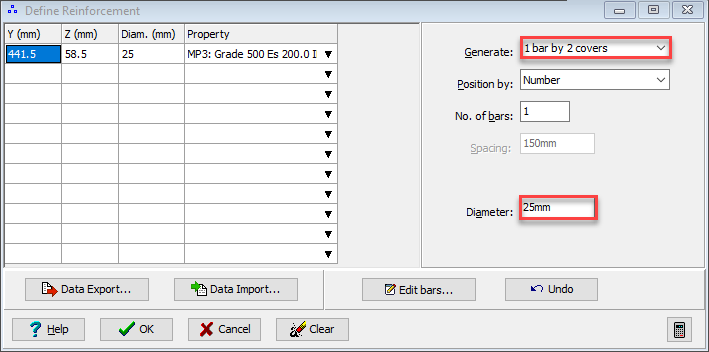
Open the Define Reinforcement form by selecting Reinforcement in the navigation tree.
-
Change the Generate option to “1 bar by 2 covers” and change Diameter to “25mm”.
-
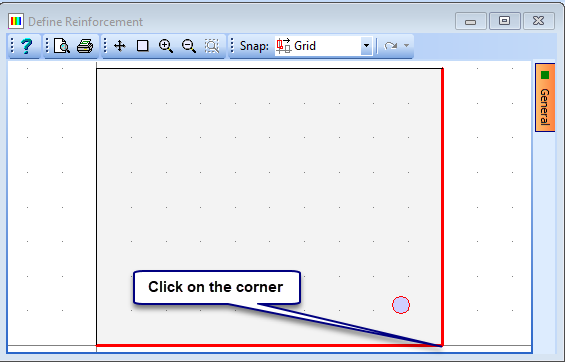
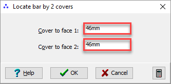
Click on one of the corners of the rectangle in the graphics window to display a data form allowing the definition of the reinforcement cover. Set this cover to “46mm” on both faces and then close the form using ✓ OK.
-
Repeat step 9 for the other three corners noting that the cover is automatically set to the last defined.
-
Change the Generate option to “Draw Bars” and set Position By to “Number”. Set the No. of bars to “4” and leave the Diameter as “25mm”.
-
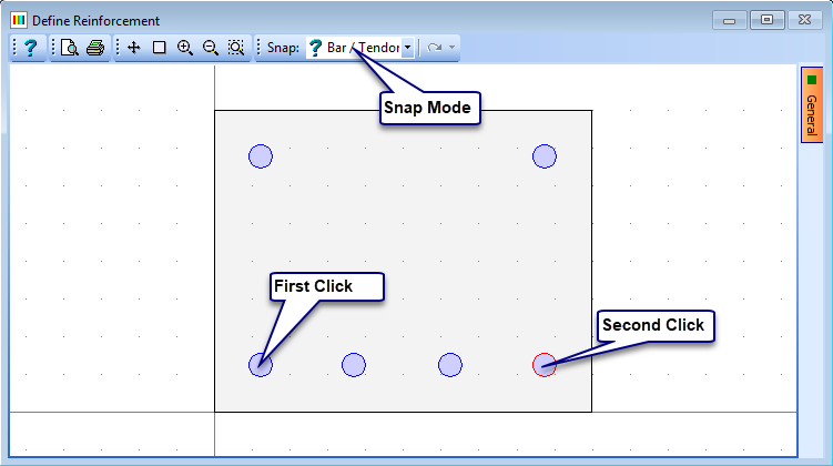
In the graphics window toolbar, set the snap option to “Bar/tendon” then click on the bottom left hand bar in the graphics window followed by the bottom right hand bar. This will create an extra 4 bars, 2 of which will be superimposed on the corner bars.
-
Repeat this with the two top corner bars.
-
Change the No. of bars to “3” and draw in the bars along the remaining two vertical edges in the same way.
-
Close the Define Bars and Tendons form using the ✓ OK button and a message should be displayed saying “Superimposed bars have been deleted”.
-
Re-open the Define Reinforcement form by selecting Reinforcement in the navigation tree.
-
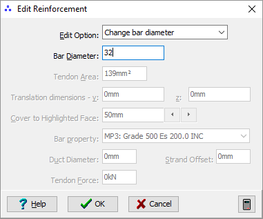
Click on the Edit bars... button and then draw a window around all bars in the graphics window by clicking once in one corner and then clicking again in the opposite corner of the rectangular section. The bars should turn red and a secondary Edit Reinforcement form should be displayed. Change the Edit Option to “Change bar diameter” and set the Bar Diameter to 32mm. Close the Edit Reinforcement form using the ✓ OK button and the bars are updated.
-
The cover to these bars has then been reduced to 42.5mm so we need to move the bars to re-establish 46mm cover. This can also be done using the “Edit Bars...” button but can only be done one face at a time. Click on Edit bars... and then window round the topmost row of bars. Change the Edit Option to “Reset Cover” in the Edit Reinforcement data form and set the cover to “46mm” before closing the form with the ✓ OK button. The cover to these bars has now been adjusted.
-
This can be repeated for the bottom row of bars and each side row, remembering to click on the Edit bars... button each time before selecting the appropriate bars. Close the Define Reinforcement form using the ✓ OK button.
-
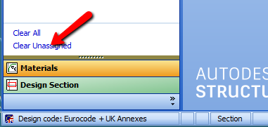
Before saving the file we may wish to remove any redundant materials that were defined by using the template. This is not generally necessary but, if required, it can easily be done by selection Materials in the navigation window and then selection the Clear Unassigned task item at the bottom of the navigation tree window. This will remove any unused materials from the materials list.
-
The data can then be saved, using the menu item File | Save as..., to a file called “My EU Example 2_3.sam”.
-
Close the program.
Summary
This is a simple example that illustrates the creation of a reinforced section which is then needed to be modified. This is a process that can happen frequently in a real design cycle. For this simple section it would probably be just as simple to delete the bars and re-specify them but for more complex sections this may be time consuming.