2.2 Voided Slab
Subjects Covered
- Creating Voids
- Continuous faces
- Reinforcing faces
- Manipulation of hook points
Outline
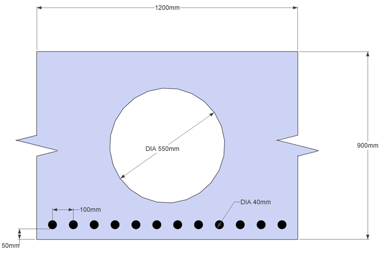
A hole can be created in a section by defining a second component, entirely contained within the first component and assigning it a “void” property. If a section is part of a larger section then the torsion property calculations need to know this, so the continuous faces must be identified. Reinforcement can be defined relative to a face with a specific diameter, spacing and cover. The section below can be created to illustrate all these aspects.
Procedure
-
Start the program and start a new section by using the main menu item File | New | Create From Template and selecting “EU Section”.
-
Use the menu item File | Titles... to set the title as “Voided Slab Section” with a sub-title of “Example 2.2” and change the job number to 2.2. Click on “OK” to close the titles form.
-
Select Design Section at the bottom of the navigation window and use the + button at the top of the window to create a new section element as a Parametric Shape.
-
This will display a form (with graphic) showing a rectangular shape. Set the width to “1200mm” and depth to “900mm” and in the Property field select grade C32/40 concrete.
-
In the Graphics window click on the two vertical edges (once) and the solid lines change to dashed lines. This signifies that these are continuous faces. If the lines are not dashed but bold, then this means they have been clicked on twice and this signifies the edge is part of the “soffit”. If this happens then click on the lines again until they become dashed.
-
Now set the Hook Point Reference to “0” and the X and Y coordinates also to “0”. This moves the origin to the centre of the shape.


-
Close this form using the ✓ OK button.
-
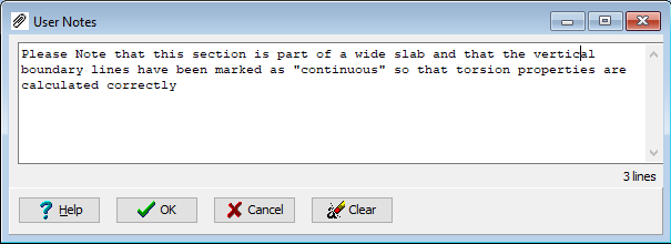
Use a right mouse click in the navigation window to display the context menu and select “Notes...”. Type in the note below and then close the notes window with the ✓ OK button.
-
Create a second parametric component using the + button, as before, and change the shape to “Circle” in the Shape Reference field with a diameter of “550mm”.
-
Again set the Hook Point Reference to “0” and the X and Y coordinates also to “0”, which will make the two shapes concentric.
-
Leave the Property of this second component as “Void”, as this will form the hole, and then close the Define Section Element form using the ✓ OK button.
-
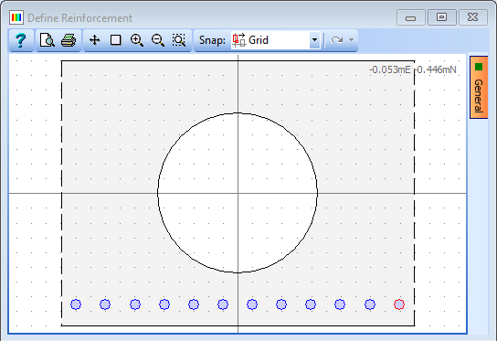
Open the Define Reinforcement form by selecting Reinforcement in the navigation tree.
-
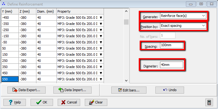
Change the Generate option to “Reinforce Faces” and change Position By to “Exact Spacing” with a spacing of “100mm”.
-
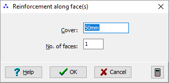
Set the Bar diameter to “40mm” and then click on the bottom face of the rectangle in the graphics window to display a secondary data form allowing the definition of the reinforcement cover. Set this cover to “50mm” and then close the secondary form using ✓ OK.
-
Note that the reinforcement material property is automatically selected (but could be changed if a second reinforcement property is defined).
-
Close the Define Reinforcement form using ✓ OK.
-
Save the data file using the File | Save as... menu item as “My EU Example 2_2.sam”.
-
Close the program.
Summary
Voided slab sections are often used to represent the longitudinal stiffness of a grillage beams. It is important that the torsion properties are calculated correctly and that if “Cracked” section properties are required then the reinforcement is correctly defined.