8.5 Defining Box Girder with DXF File
Subjects Covered
- Preparing DXF files for Autodesk Structural Bridge Design finite element structures
- Importing DXF files into Autodesk Structural Bridge Design to define finite element structures
- Design Line
- Carriageway definition
- Local axes
- FE properties
Outline
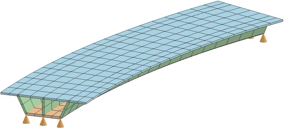
The box girder bridge below has a slab thickness of 200mm and a bottom flange thickness of 275mm. The thickness of the webs is 250mm. The structure is modelled using 3D shell finite elements. The geometry of the structure is complicated with the slab (curved on plan) and sloping webs of the box girders. A structure with such geometry would be difficult to define directly in Autodesk Structural Bridge Design. However, such geometry is relatively easy to define in AutoCAD. Hence, a DXF file has been prepared in AutoCAD using a set of specialised commands which are loaded into AutoCAD. The DXF file will be imported into Autodesk Structural Bridge Design to define the geometry of the structure.
Below is the drawing file containing the geometric data for the finite elements. Note that Autodesk Structural Bridge Design will recognise only elements defined using either the specialised commands, or individually drawn 3D FACE entities, as finite elements when data from the DXF file is imported into Autodesk Structural Bridge Design.
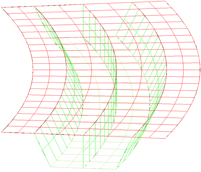
Below is an outline of the preliminary steps that can be followed to create a DXF file in AutoCAD for a simple finite element mesh. Note that in these steps commands that are typed into AutoCAD are in blue for clarity in this document.
Procedure
Defining a DXF File for an FE Model in Autodesk Structural Bridge Design
- Open AutoCAD.
- Define the drawing limits.
- Draw 3D lines and arcs in layer “0” to represent the boundary of the deck.
- Set the system variables Surftab1 and Surftab2 to define the mesh density and then use Edgesurf to create a mesh by clicking on the 4 edges of the boundary line starting with the bottom edge and working around the edge of the structure in an anti-clockwise direction. This divides the deck along the lines that define the mesh.
- Define a new drawing layer (Colour eg Red) and name it say, “DECK".
- Make the DECK layer the current layer end then “Explode” the mesh which will create 3DFaces in the DECK layer.
- Repeat a similar process for the Bottom Flange in a different layer with a different name and colour.
- Create boundary lines between the two layers and follow a similar process to create 3 meshes representing the 3 webs and explode them into a new layer, named say “WEBS”.
- Save the model as a dxf file.
-
Save the DWG file and close AutoCAD.
Importing the DXF File into Autodesk Structural Bridge Design to Create an FE Mesh
Below are steps describing how data is imported into Autodesk Structural Bridge Design from a DXF file to define a finite element model.
-
Start the program and from the main menu select File | New | Create from Template and select “EU Project”.
- In the main menu select File | Titles... to set the Project Title as “Box Girder from DXF file” with a sub-title of “Example 8.5” and a Job Number of “8.5”. Also add your initials to the Calculated by data item.
- Click on ✓ OK to close the Titles form.
- In the main menu select Data | Structure Type | Refined Analysis.
- Change the navigation window to Structure Definition and then click on the Import Model
 icon in the toolbar to open the Import Model form.
 - Select the “Bridge Structure” radio button. This will ensure that all members in the Z=0.0 plane are automatically assigned as deck members when the data is imported into the program.
- Click on the Browse button and open the supplied DXF file with a name of “BoxGirder.dxf”.
- Click on the Next button to move to the next form.
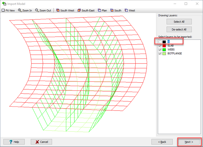
- Untick the tick box for layer “0”. The tick boxes for all other layers are ticked.
-
Click on the Next button to move to the next form.
-
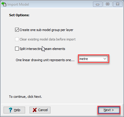
Ensure that the One linear drawing unit... field is set to “metre” and click on the Next button to move to the next form.
-
When the data has been imported click ✓ OK to close the Import Model form.
- The Member Details form will open automatically. By scrolling down the table on the form we can see that the tick boxes in the Deck column are ticked automatically for those finite elements that form the deck. Hence, these finite elements will be considered as deck elements in the calculation of influence surfaces and the application of loads.
-
Click ✓ OK to close the Member Details form.
Defining the Carriageway and Span End Lines
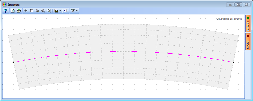
We will define a design line which will be used to align the carriageway.
-
Select Structure in the navigation window and click on the
 button to select “Design line” to open the Define Design Line form.
 - Click the “+” button at the bottom of the data form and in the resulting form select the Arc radio button and click the Next> button.
- Select the 3 points on curve radio button and click the Next> button.
- Set the Snap field at the top of the graphics window to “Intersection” and select 3 points along the centre of the deck in the graphics window by clicking on the point at the left hand end of the deck, a point near the centre of the span and then at the right hand end of the deck.
-
Click Next> and ✓ OK to close all the forms.
Next we will define the carriageway that will run over the structure.
-
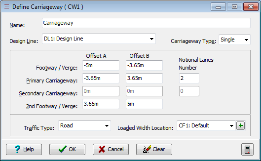
Click on the "+" button and select “Carriageway” from the dropdown menu to open the Define Carriageway form and set the fields to the selections and values shown below.
(Note that the traffic flow direction is indicated by a triangular arrow head in each notional lane and clicking on each of the arrows until they are double-headed will show that traffic can flow in either direction. However, in this example we will leave the lanes as single direction).
-
Click ✓ OK to close the Define Carriageway form.
The next step is to define the location of the span end lines.
-
Click on Structure in the navigation window and click on the
 toolbar button to select “Span End Lines”. This will open the Define Span End Lines form.
 - Click on the bottom left and top left-hand corners of the structure on the graphics window. This will draw a heavy black line.
- Repeat this for the righthand abutment to define the span end lines.
-
Click ✓ OK to close the form.
Defining Supports
Next we will define the 6 support nodes for the structure.
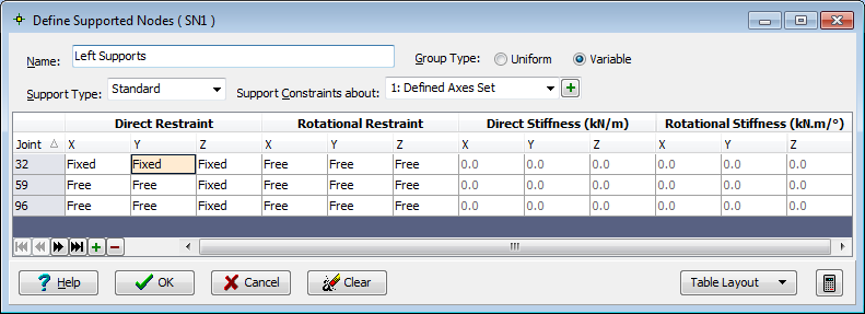
The supports will be defined such that the 4 outer supports will be resisting vertical loads only. The support node at the centre of the left hand end of the structure will be fixed in the radial and tangential direction.
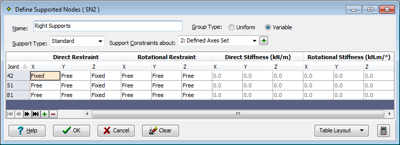
The support node at the centre of the right hand end of the structure will be fixed in the radial direction and free in the tangential direction.
It is recommended that the user takes note of the orientation of the local axes of the support nodes when interpreting support reaction results.
-
Click on Structure in the navigation window and then click on the
 button to select “Supported Nodes”.
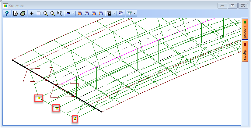
 - Ensure that the Select: field is set to “All Joints” and select the 3 nodes at the left hand end of the structure as shown below.
- In the first row of the support table, change the support conditions so that only the _DZ_ direction is fixed. Change Group Type to “Variable” then click on the middle of the 3 nodes (node 32).
-
Change the support conditions for this node so that it is also fixed in DX and DY.
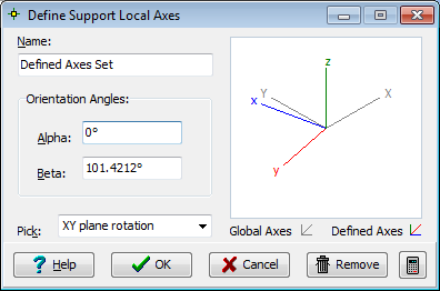
The orientation of the supports will be altered such that the local y axis is tangential and the local x axis is radial.
-
Click on the “+” button next to the Support Constraints about field to open the Define Support Local Axes sub-form.
- Click on the bottom right support node (node 59) then on the bottom left support node (node 96). Note that the angle in the Beta field has changed to 101.4212 degrees.
-
Click ✓ OK to close the sub-form.
-
Change Name to “Left Supports” and click ✓ OK to close the Define Supported Nodes form.
The support nodes at the right hand end of the structure will now be defined.
-
Click on the
 button and select “Supported Nodes” again.
 -
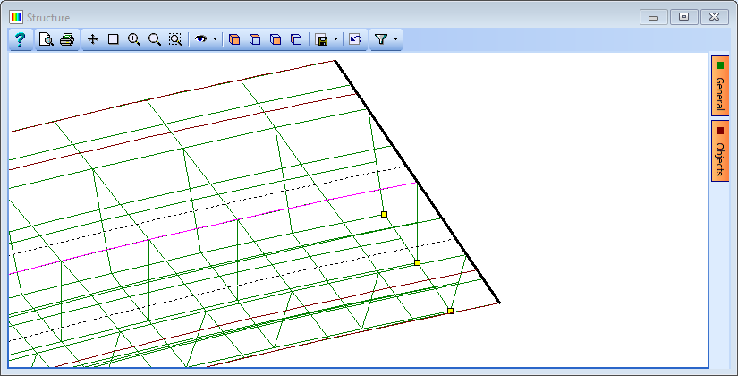
Select the 3 nodes at the right hand end of the structure as shown below.
-
In the first row of the support table, change the support conditions so that only the _DZ_ direction is fixed.
- Change Group Type to “Variable” then click on the middle of the 3 nodes (node 42).
-
Change the support conditions for this node so that it is also fixed in DX.
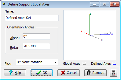
The orientation of the supports will be altered such that the local y axis is tangential and the local x axis is radial.
-
Click on the “+” button next to the Support Constraints about field to open the Define Support Local Axes sub-form.
- Click on the bottom left support node (node 51) then on the bottom right support node (node 81). Note that the angle in the Beta field has changed to 78.5788 degrees.
-
Click ✓ OK to close the sub-form.
-
Change Name to “Right Supports” and click ✓ OK to close the Define Supported Nodes form.
Properties
There are three properties to define.
- The 250mm thick isotropic FE property for webs.
- The 200mm thick isotropic FE property for slab.
-
The 275mm thick isotropic FE property for bottom flange.
-
Change the Structure navigation window to Structure Properties and then click on the
 button at the top of the navigation window to select Finite Element.
 - In the Finite Element Properties form, change the Thickness: to “250”, ensure the Material property is the grade C32/40 concrete and change the Name to “250 thick FE”.
- Click on the Filter toolbar dropdown button and select “WEBS”. Note that sub model groups were automatically created for each of the layers in the imported DXF file.
- Box around the whole structure to assign this section property to the webs.
- Click ✓ OK to close the form.
- Assign the section properties for the other sub model groups by following a similar procedure. When all of the section properties have been assigned select “Select All” to turn the filter off.
- The structure file can be saved at this point by selecting the menu item File | Save as..., and saving the file with a name of “My EU Example 8_5.sst”.
- Additional data for the Basic Loads etc. can be defined to complete the structure file. See examples 6.5 and 10.2 for further information on defining finite element structure files.
Summary
This method enables users to import data from a DXF file to define a finite element box girder structure in Autodesk Structural Bridge Design. The supports are assigned to the structure and adjusted to suit the layout of the structure. Section properties are also assigned to the structure. Note that a virtual member could be created within the finite element analysis model. See example 10.2 for information about this.