8.2 Steel Composite Beam Grillage Integration
Subjects Covered
- Transfer of results from grillage analysis model to steel composite beam load tables
Outline
In this example we are going to follow a procedure for carrying out a Eurocode traffic load optimisation for bending and shear in two beams, transferring the analysis results to the steel composite beam load effect tables for subsequent design checks.
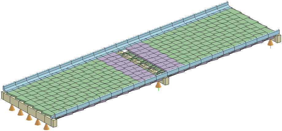
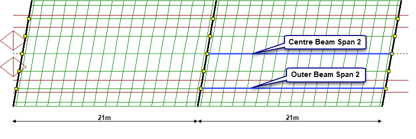
The 2 span steel composite structure has already been defined in a pre-prepared data file which contains materials, design sections, design beams, structure definition and structure properties. We are going to use the automated load optimisation to create live loads on the structure that can be used in the design of two of the beams. The structure is symmetrical so we will only consider the centre beam and outer beam of span 2 and we will determine worst effects for just three points on each:
- Sagging bending moment at mid-span
- Hogging bending moment at the pier
- Vertical shear at the node next to the pier (not coincident with it)
For each of the two beams we will determine the influence surfaces, carry out the load optimisation for the three effects with regard to creating gr5 load combinations using an SV80 vehicle and transfer the analysis results back to the design beams.

Procedure
Import The Structure
- Start the program and open the pre-prepared data file “EU Example 8_2 Grillage.sst”.
-
Use the File | Titles main menu item to set the Project Title to “Grillage with Automated Live Loads”, a subtitle of Example 8.2, a job number of “8.2” and put your initials in the Calculations by: field.
Define Influence Surfaces and Load Optimisation
We will now create some influence surfaces and generate live load patterns using the load optimisation in the program. The first step is to define the influence surfaces we want to generate.
-
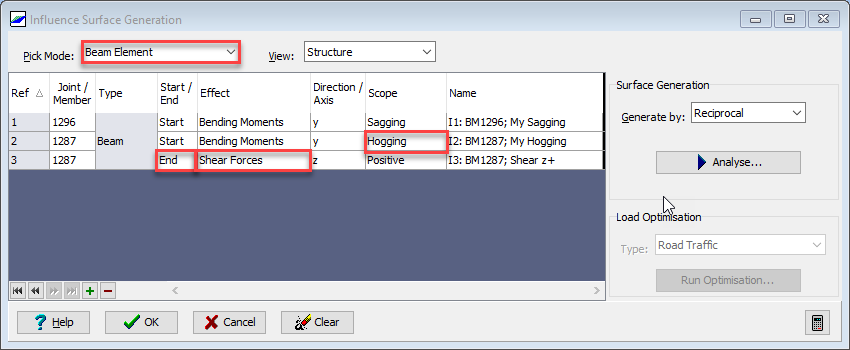
Click on the Data | Influence Surface... menu item to open the Influence Surface Generation form. Set Pick Mode to “Beam Element” then click on the beam three elements indicated below in span 2 in the graphics window. The short element will need clicking on twice to make the third entry for shear.
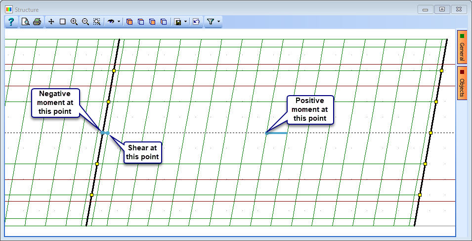
This will give three rows of data in the influence table.
-
In the second row change Scope to “Hogging” and Select “No” in the confirm form that asks if other things need changing.
-
In the third row change Start/End to “End” and Effect to “Shear Forces.”
The next step is to analyse the structure and generate the influence surfaces.
-
Set Generate by to “Reciprocal” and click on the Analyse button. A progress box will open.
-
Click on the Done button when the analysis has completed. The graphics window will now show the influence surface for the first member selected.
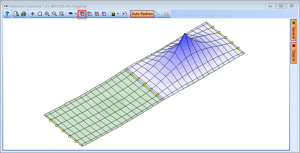
Next we will compile the loading patterns for the influence surfaces we have just generated.
-
Set Type: to “Road Traffic” then click on the Run Optimisation... button to open the Road Traffic Load Optimisation form.
- Click the Groups and Limit States icon at the top and select the option to “Clear all”.
- Then tick the ULS-STR/GEO(B) | Persist/trans | gr5 option as well as the SLS | Characteristic | gr5 option.
- The Scope option should be set to “Matching”.
- The Load Model 3 Special Vehicles: option should be set to “SV80”.
-
Click the Compile Loading Patterns button to run the load optimisation. A relatively limited range of load types has been considered to minimise the amount of data but many options can be run at the same time if required.
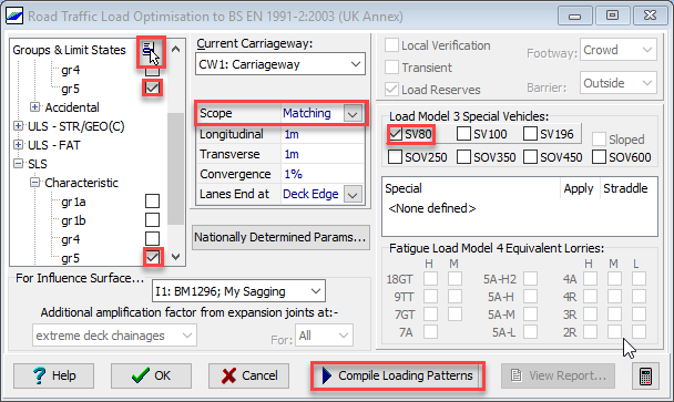
This should create all the load cases needed for the 6 combinations requested (3 ULS 3 SLS). The loading patterns can be seen in the graphics screen for each of the cases by selecting the correct influence in the Influence Surface Generation form.
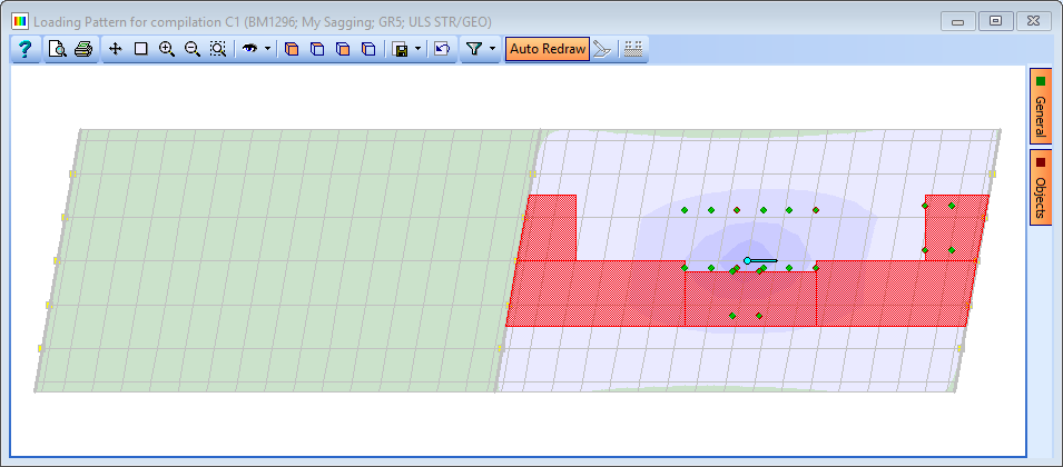
Click on ✓ OK on the Load Optimisation and ✓ OK on the Influence Surface Generation forms to save the loads that have been created.
The load case that have been created now need to be solved.
-
From the main menu select Calculate | Analyse Structure.... The Activate Loading Sets form will open. This allows you to select which loading sets you want to solve. Each time the load optimisation is run, a loading set is automatically generated for the load cases produced by that run.
-
Ensure that the appropriate loading set is ticked before clicking on the ✓ OK button.
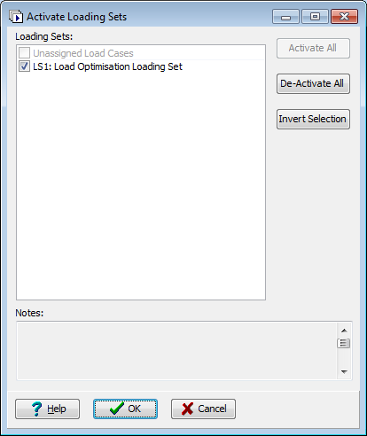
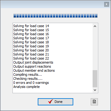
The program will open a form showing the progress of the analysis. Once the analysis has completed, click on the Done button.
The analysis results can be viewed with the results viewer if required, but the main purpose of this example is the transfer the bending moments and shear forces to the Design Beams.
Transfer results
-
In the main menu select Calculate |Transfer Results... to open the Transfer Results form. In the graphics window click on the centre beam in span. It will be highlighted in red in the graphics and will be reflected in the data form.
In the lower part of this data form it is necessary to match the analysed load cases/combinations with the appropriate load effects table in the design beams.
-
Results transfer can be completed in defined sets and these sets can be saved as separate items.
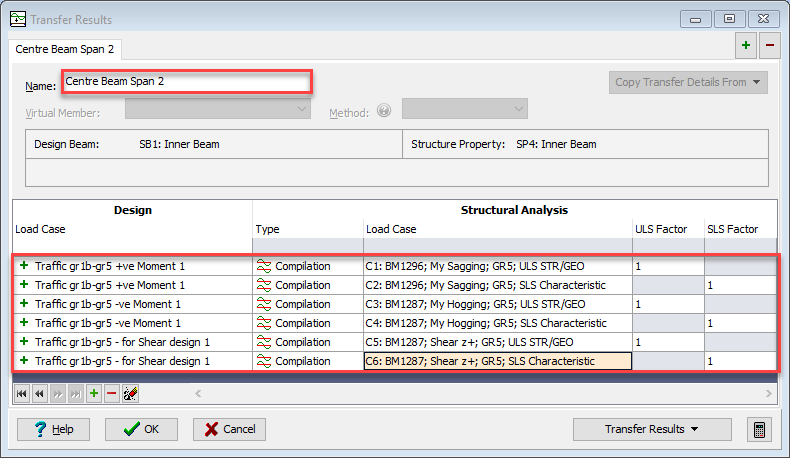
- Set the Name field to “Centre beam Span 2”.
- There are 6 combinations to transfer (3 ULS 3 SLS) so click on the “+” button at the bottom of the form to add six rows to the table.
-
Fill in the six rows of data as shown noting that although there are six separate load compilations to transfer, there will only create 3 load effects tables in the design beams as both ULS and SLS are shown in the same table.
-
Use the Transfer Results | Transfer Current Set to Design Beam button to transfer the results and “OK” the information message before closing the Transfer Results form with the ✓ OK button.
-
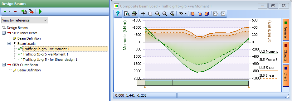
To check that these results have been transferred correctly change the navigation window to Design Beams and note the three Beam Loads objects for “Inner Beam”.
Repeat for Other Design Effects/Beams
The whole process can be repeated for other design effect on different beam. However, it is required to create the same design effects for the Outer beam.
-
In the main menu select Data | Influence Surface to open the Influence Surface Generation form.
- Change the three Joint/Member to 1332, 1323 and 1323 to give the similar locations and effects on the outer beam, (confirming that the influences will need to be regenerated.
- Click the Analyse button to create the influence surfaces and select the Done button to complete the analysis.
- Click on the Run Optimisation button and select the Compile Loading Patterns button on the new form. It is important not to overwrite existing loads so answer “No” to this.
- After the new load patterns have been created click the ✓ OK button on both the Load Optimisation and Influence Surface forms.
-
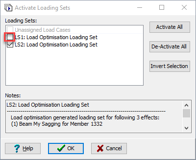
The new load cases need analysing so use the main menu Calculate | Analyse Structure to open the Active Loading Sets form. There is no need to re-solve the first loading set, so un-tick it and click on the ✓ OK button.
The resulting load effects can also be transferred to the outer Design Beam.
-
In the main menu select Calculate |Transfer Results... to open the Transfer Results form.
- Add a new transfer set by clicking on the “+” button in the top right of the form and define the Name as “Outer Beam Span 2”.
-
Click the Copy Transfer Details From button and select “Centre Beam Span 2” and the in the graphics window click on the outer lower beam in the second span.
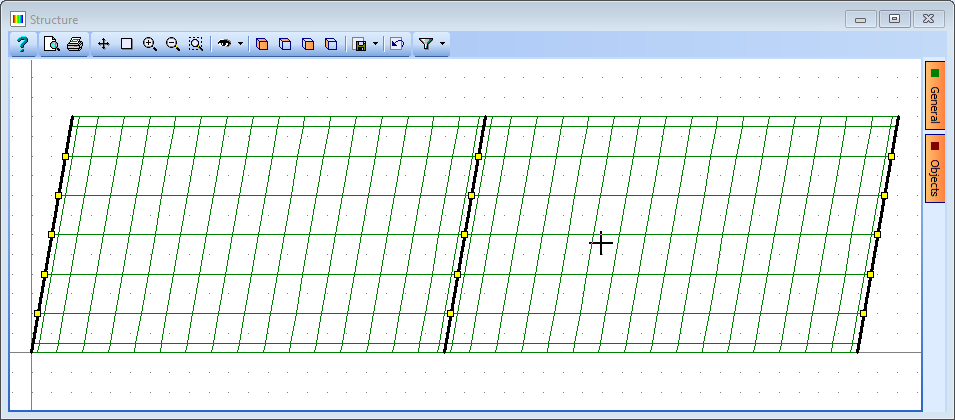
-
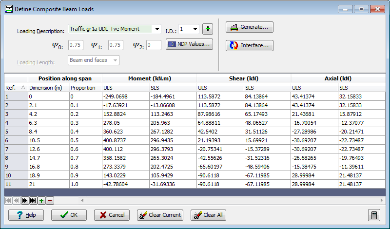
The Structure Analysis load case in the form need changing to combinations 7 to 12 but then the transfer of results can then be completed by clicking on the Transfer Results button and selecting Transfer Current Set to Design Beam.
-
Click on the Transfer Results button and select “Transfer Current Set to Design Beam” to complete the task of entering the results in the “Outer Beam” load effects table. _OK_ the information message.
- To check that these results have been transferred correctly change the navigation window to Design Beams and note the three Beam Loads objects for “Outer Beam”.
- Save the data file as “My EU Example 8_2.sst”.
- Close the program.
Summary
In this example a pre-prepared data file containing a 2 span steel composite bridge deck was opened and live loads were generated using the live load optimisation feature. The critical load effects for the centre beam of span 2 were calculated and transferred to the appropriate tables in the design beam. This was repeated for the outer beam of span 2.