4.4. Prestress Beam Definition (Advanced)
Subjects Covered
- Prestress beam
- Edge beam; Exterior beam
- Varying cross section
- Merge by stage
- Edge upstand
- Section locations
- Remove unwanted tendons
- Debond tendons
- Define reinforcement
- Curtailment of reinforcement
- Change reinforcement properties
Outline
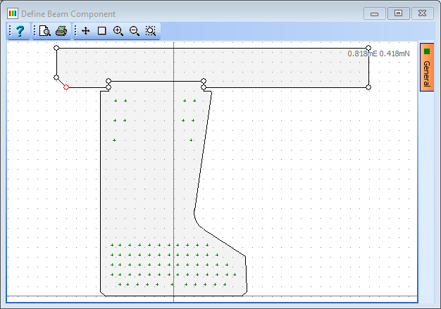
A prestressed concrete edge beam and insitu concrete slab, upstand and infill are shown below. The precast beam is a YE5 standard beam with just 4 tendons in the top of the beam and two rows of tendons in the bottom. The positions of the tendons are in the manufacturers default locations and the centre four tendons of the second row are debonded along the first 3.5m from the beam ends.
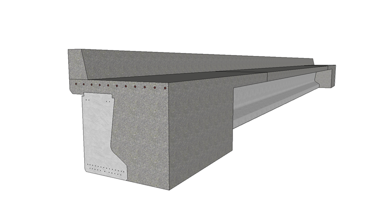
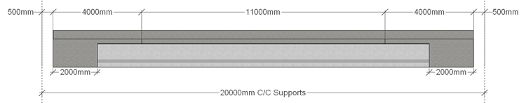
The precast beam is 19m long but, when the insitu diaphragm is cast, the composite beam spans 20m between the centre lines of the integral supports. It is constructed using grade C50/60 concrete and prestressed with standard wire strands, each having an effective area of 150mm2 and a nominal radius of 16mm. The characteristic strength of each tendon is 1861MPa and they are set to have a relaxation of 2.5% at 1000 hours.
The slab is cast in two stages: the first (stage 1a) being the central 11m portion and the second (stage 1b) being the two ends together with the infill between adjacent beams (which extends 2.0m along the beam from each end). The upstand (stage 2) is then added as an additional stage and is cast along the complete length. All insitu concrete is grade C32/40. Reinforcement is placed in the slab at each end of the beam, as shown, to resist the hogging moment due to the integral abutments. This reinforcement extends 5.0m into the slab from both ends. Standard grade 500 reinforcement is used.
Procedure
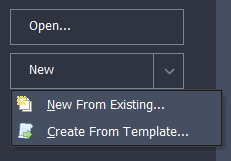
Start the program and create a new beam by selecting the New drop down button item Create From Template and pick the “EU Pretensioned” template.
Use the menu item Design Beam | Titles to set the beam title to “Prestress Beam - Advanced” with a sub-title of “Example 4.4”. Also set the Job Number to “4.4” and add your initials to the Calculated by data item if necessary. Click on ✓ OK to close the Titles form.
Define Materials
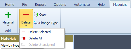
In the Materials navigation window select the redundant material (i.e. the Structural Steel material, MP5) in the navigation tree and delete it by either pressing the Del key or clicking Delete | Delete Selected in the menu bar.
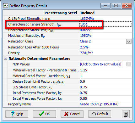
Select the material “MP4:” from the navigation tree to open the prestress steel material properties. Change the Characteristic Tensile Strength, fpk to “1861MPa”. Ensure Relaxation Loss After 1000 Hours is set to “2.5%” and the Relaxation Class is set to “Class 2”.
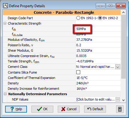
Select the material “MP2” from the navigation tree to open the precast concrete properties. Change the Grade C40/50 concrete to grade C50/60 by changing the Characteristic Strength, fck in the data form to “50”.
In the Design Beam navigation window select Beam Definition to display the Pre-tensioned Beam Definition form.
Set the Beam Length to “19” and the Support to beam end face to “-0.5” at both ends and press the 'Enter' key. Note the Support c/c is shown as 20m.
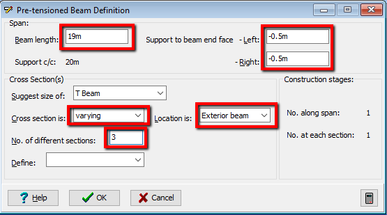
In the Location is field select “Exterior beam” from the drop down list and set Cross section is to “varying”. The No. of different sections should be set to “3”.
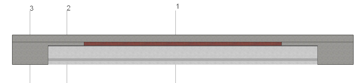
The first section is that at the centre of the beam with a precast beam and stage 1a insitu concrete representing the slab. The second section is that section where there is no infill but the slab is stage 1b. The third section is the same as section 2 but the slab is now extended to include the infill concrete. The upstand (Stage 2 concrete) is present in all three sections.
Define Cross Sections and Locations
To create section 1, open the Pre-tensioned Beam Section Definition form by selecting “Section 1” from the drop down list in the Define: field.
Click the table insert + button and select “PC beam – Standard” from the Component column list to open the Define Precast Beam Component form. Here set the Concrete beam range: to “YE Beam” and the Shape no. within range: to “YE5” and then close the form using the ✓ OK button. Ensure the Concrete Property is grade C50/60 concrete.
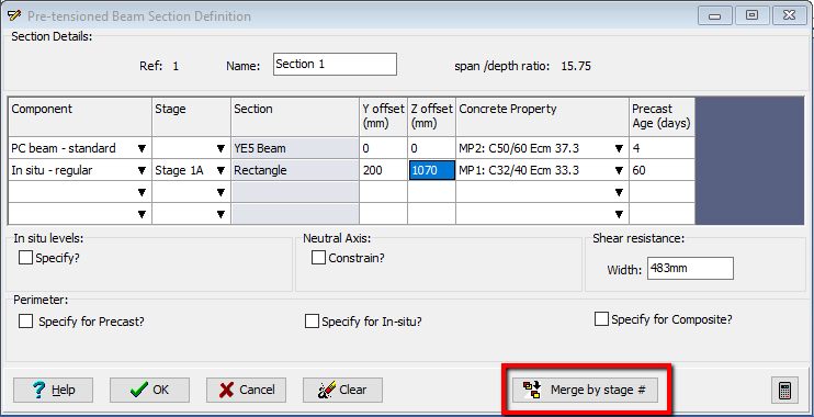
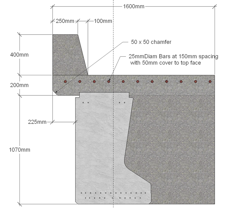
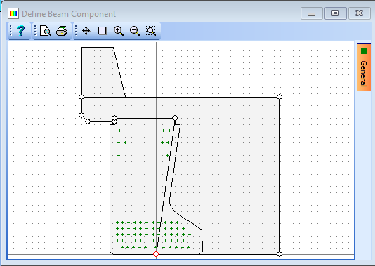
Click the table insert + button and select “Insitu – Regular” component in the new row. In the Define Precast Beam Component form set the Shape reference to “Rectangle”, the width to “1600” and the depth to “200”; then close the form with the ✓ OK button. Stage should be set to “Stage 1A” and the y & z offsets to 200 and 1070 respectively (and press the 'Enter' key). To cut the concrete out around the precast beam use the Merge by Stage button. If you cannot see the full section on the graphics press the F4 function key (after getting focus on the graphics window) to Fit the view.
The shape merge will change the in situ component from 'Regular' type to 'Define' type. To define the chamfer on the bottom left corner of the slab, add a point and then edit the coordinates to suit.
With the In Situ row selected, click on the table edit button to display the User Defined In Situ form. Click on the first coordinate (the bottom left corner of the slab should be highlighted with a red circle) and then click the small + button at the bottom of this table to add a point halfway up the left edge of the slab. Change the Z coordinate of this point to “1120”.
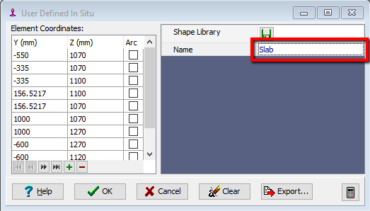
Click on the first coordinate again and set the Y coordinate of the point to “-550”. Change Name: to “Slab” and then close the Define In Situ form using the ✓ OK button. Ensure that the Property is set to Grade C32/40 Concrete.
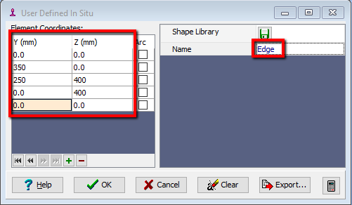
The last component to add is the upstand which is done by adding an additional defined shape. Click the table insert + button and select “Insitu – Define” component in the new row. Create a shape by clicking the small + button at the bottom of the table 5 times and then editing the coordinates to (0,0) (350,0) (250,400) (0,400) (0,0), and naming the shape “Edge”.
Close this form with the ✓ OK button.
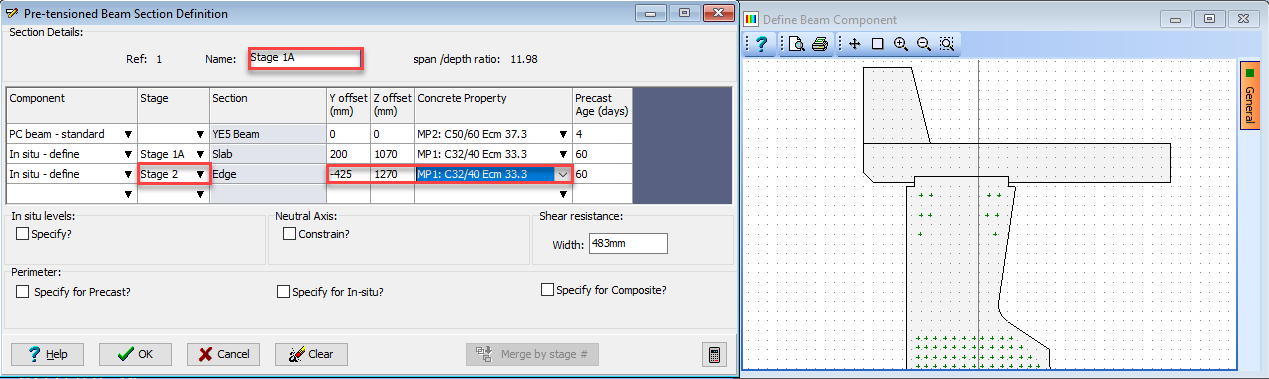
Set the Y offset to “-425” (which is the centre of the bottom edge) and the Z offset to “1270”. Also check that the material property is grade C32/40 concrete and that Stage is set to “Stage 2”.
This completes the definition of section 1 so change the Name: to “Stage1A” and close the Section Definition form with the ✓ OK button.
To create section 2 select “Section 2” from the drop down list in the Define: field. By default this will be the same as Section 1. All that is required is to change the Stage for the Slab component to “Stage1B” and change the Name: to “Stage1B”. Close the Section Definition form with the ✓ OK button.
To create section 3 select “Section 3” from the drop down list in the Define: field. By default this will be the same as Section 1.
To define the Infill concrete, which is cast together with the slab, around the shape of the precast beam it is necessary to modify the coordinates of the slab and then use Merge by Stage to remove any overlapping portion.
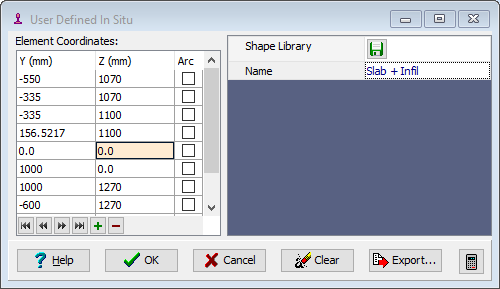
In the Component column of the second row of the table select “Insitu – define” to open up the insitu slab data form. In the graphics window, click on the bottom right corner of the slab to make the circle marker turn red. This highlights the coordinates in the table. Change the z coordinate of this point to 0. Click on the coordinate immediately before the coordinate that has just been edited and change them to (0, 0). Enter “Slab + Infill” into the Name field and then close the form using the ✓ OK button (say no to the prompt for updating the other sections). Click on the button Merge by Stage # to remove the overlapping concrete then change the Stage to “Stage 1B” (if it is not already set to “Stage 1B”) and ensure the Property is set to grade C32/40 concrete.
All that is required now to do now is ensure the Stage for the Slab + Infill component is set to “Stage1B” and change the Name to “Stage1B + Infill”. Close the Section Definition form with the ✓ OK button.
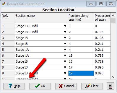
These sections now need to be located at positions along the span. This is done by selecting “Section Locations” in the Define field and filling out the data as shown below in the resulting data form. Use the table + button to create 10 rows. Please note that the first column values are selected from a drop down; entering the second column values will automatically fill the third column values. Click ✓ OK to close the Beam Feature Definition form.
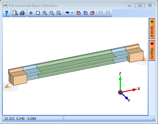
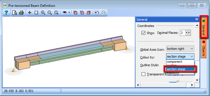
The graphics is coloured to show the different sections. This can be changed to show the stages of construction by opening the General tab of the graphics window and selecting “Section Stage” in the Colour By field.
Define Tendons
To define pre-stressing tendons open the Pre-tensioned Beam Tendon Definition form by selecting Tendons in the Define: field of the Pre-tensioned Beam Definition form.
By default all available tendon locations have a fully stressed tendon applied. To remove the tendons not required (but not the locations) set the Edit Mode field to “Insert/Remove” and then select the unwanted tendons in the graphics window by boxing around the group as shown – this will turn the small dots red. The tendons will be deleted when the 'Delete' key on the keyboard is pressed. The tendons can be replaced by doing the same but using the 'Insert' key rather than 'Delete'.
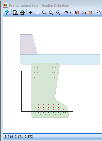

The 4 central tendons in the second row need to be debonded which is done by selecting “Debond” in the Edit Mode: field. Check the Symmetrical Elevation checkbox, set the Left: field to “3.5” (when the “enter” key is pressed it automatically updates the right end) and then window round the 4 tendons, which turns them red. The tendons are debonded beyond these locations with a right click in the graphics window and “debond” selected. They are indicated graphically as orange dots.
To see how the tendons and sections change along the beam length click once on the green arrow in the elevation graphics and drag the pointer from one end to the other. The section graphics changes accordingly. Moving the blue handles will alter the debond points. Close the Tendon Definition form using the ✓ OK button.
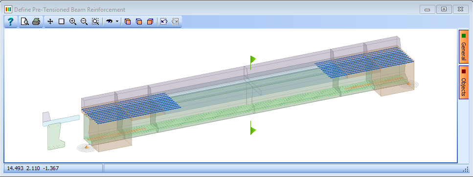
Define Reinforcement
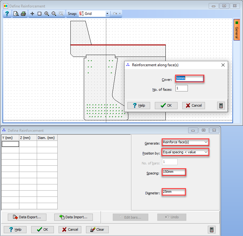
To define the reinforcement, select “Reinforcement” in the Define: field of the Pre-tensioned Beam Definition form which opens the Define Pre-tensioned Beam Reinforcement form. To create the bar positions click on the Insert Bar + button near the bottom of the form which opens the Define Reinforcement form.
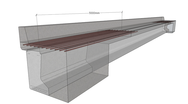
Reinforcement is required at both ends of the beam with a gap in the middle. This is achieved by defining two bars, one for each end of the beam, and setting the start and end points of each accordingly. The two bars can be located in the same position in the section but to ensure that is possible to select one bar or another, one set of bars will be defined and curtail before creating the second set of bars.
Set the Diameter: field to “25mm”, the Position by field to “Equal Spacing < value” and the Spacing field to “150mm”. Select “Reinforce face(s)” in the Generate field and then click on the top face of the slab which will open a secondary form. Accept the default value of “50mm” cover by closing this form with the ✓ OK button and the bars will then be displayed in the graphics window.
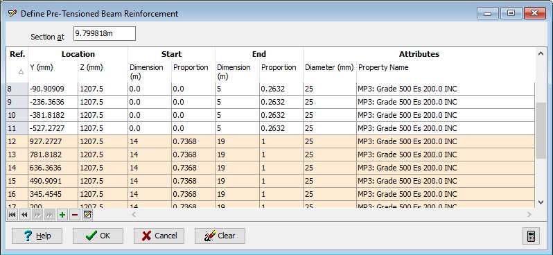
By default the reinforcement runs from one end of the beam to the other, so they need curtailing. Close the Define Reinforcement form using the ✓ OK button. Window around the top row of reinforcement, if they are not already red, in the graphics window and click on the
 icon. Check the Modify checkbox and set Dimension / End to “5” before clicking on the ✓ OK button on the sub form. We now need to create the second set of bars so move the green slider bar on the graphics to a position that does not contain reinforcement and click on the + button at the bottom of the screen.
Repeat step 17 and 18 except set Dimension / Start to “14” and Dimension / End to “19” before clicking on the ✓ OK button on the sub form.
The Define Reinforcement form can now be closed with the ✓ OK button to complete the reinforcement definition.
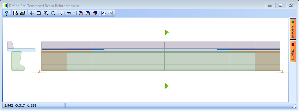
To see graphically how the reinforcement varies along the beam span, with the Define Pre-tensioned Beam Reinforcement form open, click on the green arrow in the elevation graphics and move it along the beam to display the reinforcement. (The bars can be seen by following the same procedure with the tendon definition form open). They can also be seen clearly in an Isometric view with transparency turned on.
Close all forms using the ✓ OK button and then save the file using the File | Save As menu item as “My EU Example 4_4.sam”.
Close the program.
Summary
In this example we have defined a pretensioned prestressed beam with three different cross sections. We have also defined tendons along the length of the beam and debonded them at various positions. Finally we looked at a special technique for defining curtailed reinforcement.