4.2. Steel Composite Beam Definition (Advanced)
Subjects Covered
- Steel composite beam
- span type
- end span type
- slab reinforcement
- section locations
- soffit profile
- construction stages
Outline
A composite steel girder and concrete slab is shown below.
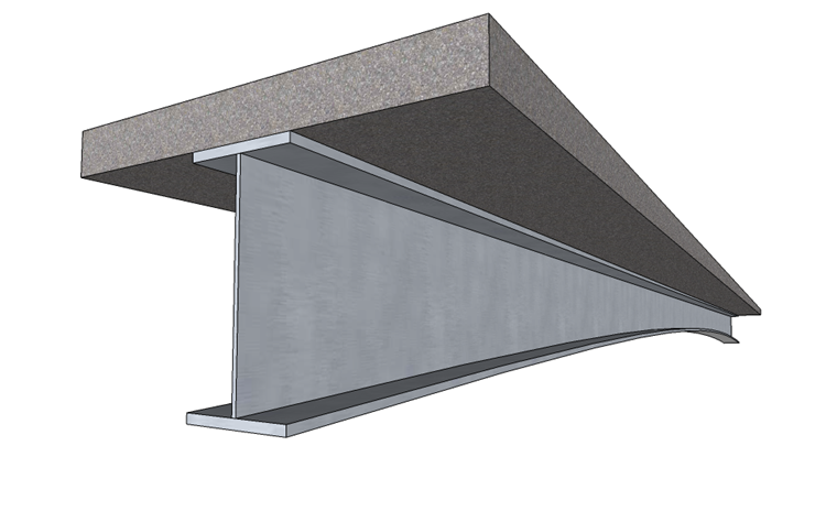
The beam is a steel plate girder of Steel Grade S355. The top and bottom flanges are 500mm wide and 40mm thick. The web is 20mm thick. The overall depth of the girder is 1000mm at the deepest section. Because of these steel thicknesses a Yield Strength of 345N/mm² will be assigned to the girder in accordance with EN10025.
The 200mm thick slab is grade C32/40 concrete and is 2000mm wide.
It is required to create two beams:
A 30m internal span which has a curved bottom flange (circular arc) such that the mid-span point is raised by 400mm. The concrete slab is cast in its length in two stages, as shown, and has longitudinal structural reinforcement of 25mm diameter bars at 200mm centres top and bottom. This reinforcement has 50mm cover and is placed in the slab only over the supports, extending 8m into the span from both ends.

A 20m end span which has a curved bottom flange (circular arc) such that the simply supported end and a point 7m from this end are raised by 400mm. The concrete slab is cast in its length in two stages, as shown, and has the same reinforcement as the first beam. This reinforcement has 50mm cover and is placed in the slab only over the continuous support, extending 6m into the span.

Procedure
Start the program and create a new beam by selecting the New drop down button item Create From Template and pick the “EU Steel Composite” template.
Use the menu item File | Titles to set the beam title as “Composite steel/concrete Beam – Advanced 1” with a sub-title of “Example 4.2a” and a Job Number of “4.2a”. Also add your initials to the Calculated by data item if necessary. Click on ✓ OK to close the Titles form.
Define Materials
- In the Materials navigation window select the S355/355 structural steel material to open the Define Property Details form.
- Enter a value of “345” in the Yield Strength field and click ✓ OK to close the form.
Define Beam
- Change the Navigation window to Design Beam and select “Beam Definition” from the navigation tree to display the Define Composite Beam data form.
- Click on the Type drop down menu and select “Continuous – internal span” from the list. Enter a value of “30m” in the corresponding Span field.
- Select the item “End span” from the SIDE SPANS – LEFT Type and RIGHT Type drop down menus and enter values of “20m” in the corresponding Span fields.
- Click on the Cross section is drop down menu and select “Varying” from the list.
- Click on the Location is drop down menu and select “Inner beam” from the list.
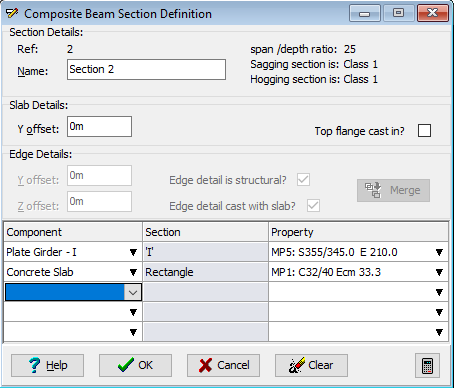
- Enter a value of “2” in the No. of different sections field. Define Cross Section and Reinforcement 11. Click on the Define drop down menu and select “Section 1” from the list to open the Composite Beam Section Definition form.
Define Cross Section and Reinforcement
Click on the Define drop down menu and select “Section 1” from the list to open the Composite Beam Section Definition form.
Click the table insert + button and in the Component column empty cell select “Plate Girder - I” from the list. This will open the Define Composite Beam Component form.
- Enter a value of “500mm” in the top flange width and bottom flange width fields.
- Enter a value of “40mm” in the top flange thickness and bottom flange thickness fields.
- Enter a value of “1000mmm” in the overall height field and a value of “20mm” in the web thickness field.
- Click on the ✓ OK button to close the Define Composite Beam Component form.
Click the table insert + button and select “Concrete Slab” from the component list. This will open the Define Composite Beam Component form.
- Click in the width field and enter a value of “2000mm”. Click in the depth field and enter a value of “200mm”.
- Click on the ✓ OK button to close the Define Composite Beam Component form.
Assign the C32/40 grade concrete material to the slab by selecting it in the second row Property column.
Click the table insert + button and select “Reinforcement” from the component list. This will open the Composite Beam Reinforcement form.
- Enter values of “25mm” in the Top Diameter and Bottom Diameter fields.
- Enter values of “200mm” in the Top Spacing and Bottom Spacing fields.
- Enter values of “50mm” in the Top Cover and Bottom Cover fields.
- Click on the ✓ OK button to close the Composite Beam Reinforcement form.
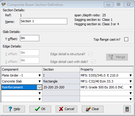
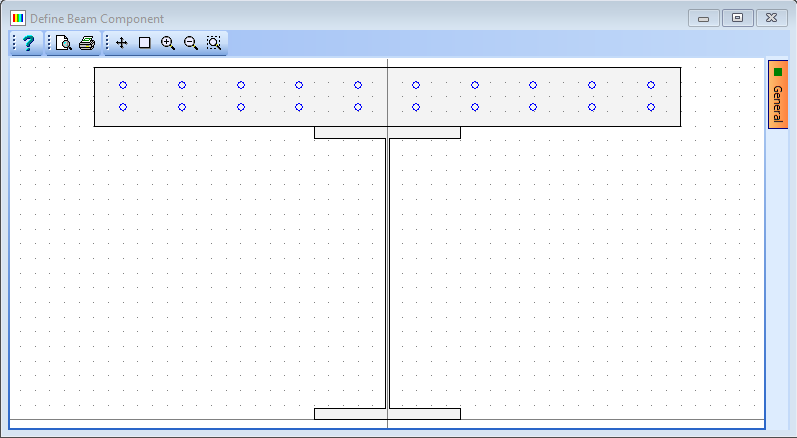
Click on the ✓ OK button to close the Composite Beam Section Definition form and select Yes on the confirmation form that is displayed.
Click on the Define drop down menu and select “Section 2” from the list to open the Composite Beam Section Definition form.
Click in the third row of the table and click on the table delete - button to remove the “Reinforcement” component.
Click on the ✓ OK button to close the Composite Beam Section Definition form and select Yes on the confirmation form that is displayed.
Define Section Locations and Soffit Profile
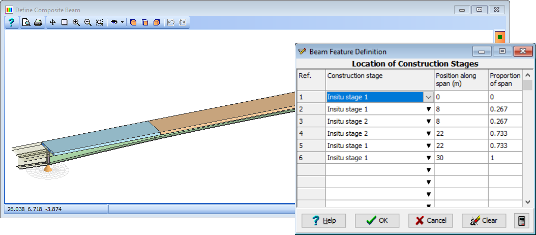
Click on the Define drop down menu and select “Section Locations” from the list to open the Beam Feature Definition form.
- Click on the Clear button to delete the current data.
- Click on the table + button 6 times.
- On the first row of the table, click in the Section name drop down menu and select “Section 1” from the list.
- On the second row, select “Section 1” and enter a value of “8m” in the Position along span field.
- On the third row, select “Section 2” and enter a value of “8m”.
- On the fourth row, select “Section 2” and enter a value of “22m”.
- On the fifth row, select “Section 1” and enter a value of “22m”.
- On the sixth row, select “Section 1” and enter a value of “30m”.
- Clicking on the icon will show the side elevation shown below. Click on the ✓ OK button to close the Beam Feature Definition form.
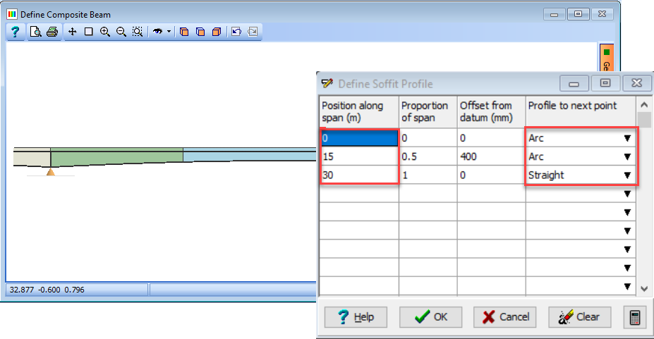
Click on the Define drop down menu and select “Soffit Profile” from the list to open the Define Soffit Profile form.
- On the second row of the table, click in the Span Position field and enter a value of “15m”.
- On the same row, click in the Offset from datum field and enter a value of “400mm”.
- On the first row, click in the Profile to next point drop down menu and select “Arc” from the list.
- Click on the ✓ OK button to close the Define Soffit Profile form.
Define Construction Stages
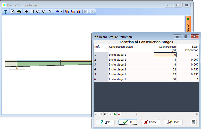
Enter a value of “2” in the No. of construction stages field. Click on the Define and locate span features drop down menu and select “Construction Stages” from the list to open the Beam Feature Definition form.
- Click on the Clear button to delete the current data.
- Click on the table + button 6 times.
- On the first row of the table, click in the Construction stage drop down menu and select “Insitu stage 1” from the list.
- On the second row, select “Insitu stage 1” and enter a value of “8m” in the Position along span field.
- On the third row, select “Insitu stage 2” and enter a value of “8m”.
- On the fourth row, select “Insitu stage 2” and enter a value of “22m”.
- On the fifth row, select “Insitu stage 1” and enter a value of “22m”.
- On the sixth row, select “Insitu stage 1” and enter a value of “30m”.
- Click on the ✓ OK button to close the Beam Feature Definition form.
Click on the ✓ OK button to close the Define Composite Beam form.
Use the File | Save As menu item to open the Save File form.
Change the filename to “My EU Example 4_2a.sam” and click on the Save button to save the data file.
Create Second Beam
Use the menu item File | Titles to set the Beam Title as “Composite steel/concrete Beam – Advanced 2” with a sub-title of “Example 4.2b”. Set the Job Number to “4.2b” and then click on ✓ OK to close the Titles form.
In the Design Beam navigation window select “Beam Definition” from the navigation tree to display the Define Composite Beam data form.
Click on the MAIN SPAN Type drop down menu and select “Continuous – end span” from the list. Enter a value of “20m” in the corresponding Span field and press 'Enter' on the keyboard. Click on the Yes button on the two confirmation messages that will appear.
Select the item “Internal span” from the SIDE SPANS – LEFT Type drop down menu and enter a value of “30m” in the corresponding Span field.
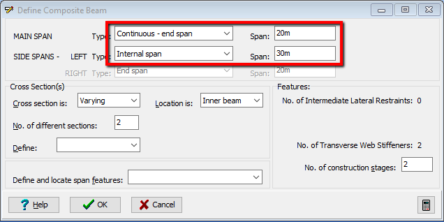
Click on the Define drop down menu and select “Section Locations” from the list to open the Beam Feature Definition form.
- Click on the Clear button to delete the current data.
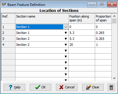
- On the first row of the table, click in the Section name drop down menu and select “Section 1” from the list.
- On the second row, select “Section 1” and enter a value of “5.3m” in the Position along span field.
- On the third row, select “Section 2” and enter a value of “5.3m”.
- On the fourth row, select “Section 2” and enter a value of “20m”. Click on the ✓ OK button to close the Beam Feature Definition form.
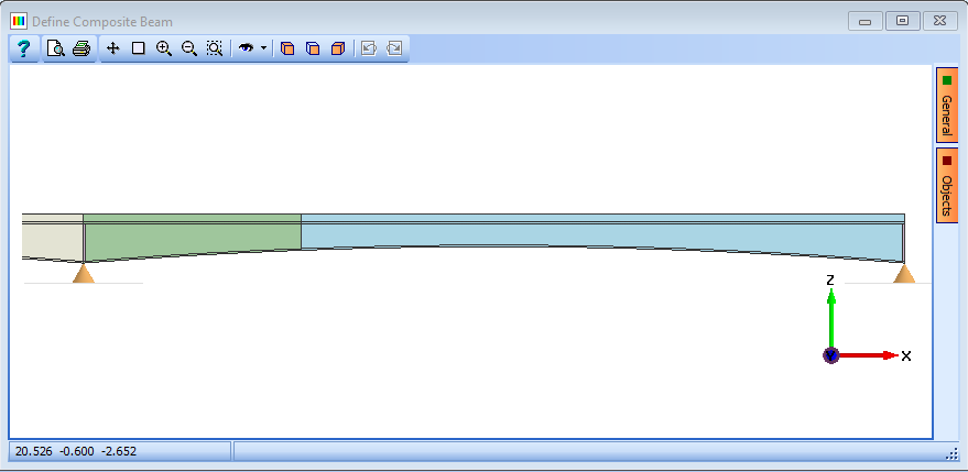
Change Soffit Profile and Construction Stages
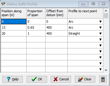
Click on the Define drop down menu and select “Soffit Profile” from the list to open the Define Soffit Profile form. Click on the “Clear” button to delete the current data and click on Yes on a Confirm form that may appear.
- On the second row of the table, click in the Position along span field and enter a value of “13m”. On the same row, click in the Offset from datum field and enter a value of “400mm”.
- On the third row of the table, click in the Position along span field and enter a value of “20m”. On the same row, click in the Offset from datum field and enter a value of “400mm”.
- On the first row, click in the Profile to next point drop down menu and select “Arc” from the list.
- Click on the ✓ OK button to close the Define Soffit Profile form.
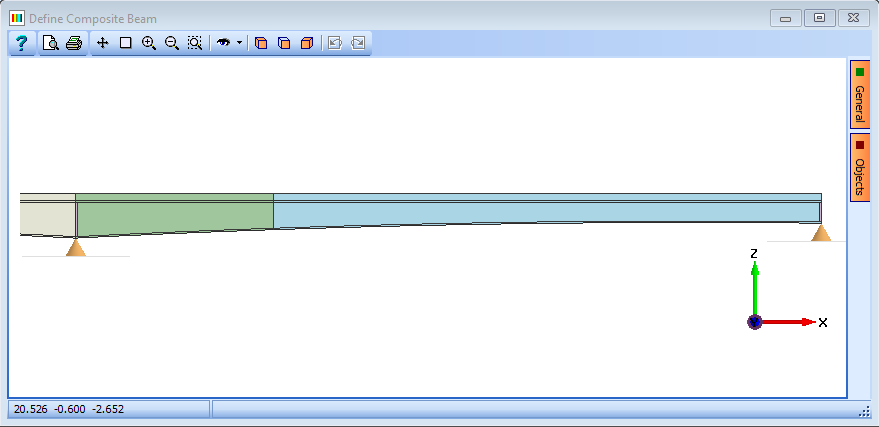
Click on the Define and locate span features drop down menu and select “Construction Stages” from the list to open the Beam Feature Definition form. Click on the Clear button to delete the current data.
- On the first row of the table, click in the Construction stage drop down menu and select “Insitu stage 1” from the list.
- On the second row, select “Insitu stage 1” and enter a value of “5.3m” in the Position along span field.
Click on the ✓ OK button to close the Define Composite Beam form.
Use the File | Save As menu item to open the Save File form.
Change the filename to “My EU Example 4_2b.sam” and click on the Save button to save the data file.
Close the program.
Summary
In this example we have created a steel composite beam for an internal span with a soffit profile and defined construction stages. We then use this file as a basis for a second steel composite beam, this time for an end span with a different soffit profile and construction stage locations.
It is important to realize that if the reinforcement had been the same for the full length of the beam the section could have been described as “Uniform” and only one section defined – despite the web varying in depth due to the bottom flange profile. The section variation is used to model sudden changes in section such as flange and web thickness changes and curtailment of reinforcement.
The reason for defining span arrangements and adjacent span lengths in the Define Composite Beam form is that the program needs this information when calculating the effective breadth of the concrete flange, used in stress calculations. The Location definition of whether the beam is an “Inner” or “Outer” beam is needed for the same reason and if the beam is used in a line girder analysis it influences the calculation of distribution factors.