5.1 Steel Composite Beam Design
Subjects Covered
- Steel composite beam
- Construction stage loads
- Generate loads; import loads
- Differential temperature profile; shrinkage and creep
- Shrinkage strain
- Design for construction stages
- Design for Eurocodes live load
- Design for vertical shear
- Combined bending and shear
- Longitudinal shear
Outline
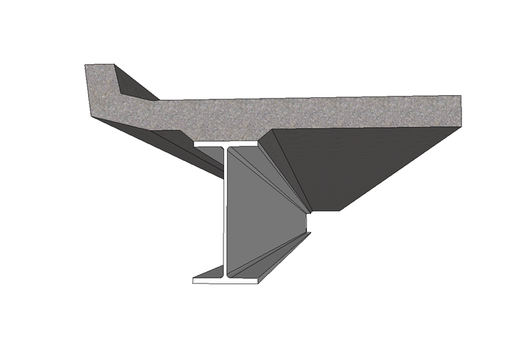
A composite steel girder and concrete slab is shown below. The beam forms a simply supported span and the concrete slab (with haunch) is cast in one. The concrete edge is cast (defined as the “string course”) after the slab concrete has hardened.
The bending and shear effects due to dead load and superimposed dead load (3.2kN/m) are created at 21 points along the span using the “Generate” feature in the program. There is a temporary load of 1.44kN/m which is applied during the beam construction but removed once the concrete has hardened. This represents temporary construction loads and the water in the wet concrete.
Max live load moment (with associated shears) and shear effects (with associated moments) have been prepared in an external ASCII file as envelopes.
There are no secondary effects due to differential temperature and shrinkage, as the beam is statically determinate, but the primary stresses need to be included for both, where appropriate. The temperature profile to be applied to the section is in accordance with EN 1991-1-5, using a 75mm thick finishing. The profile will need adjusting, as described in example 3.3, so that the edge detail is at a constant temperature and the actual profile starts at the top of the slab. The shrinkage strain for the concrete, for the calculation of differential shrinkage, is to be set to -0.00025.
It is required to check the applied effects of bending and shear against ultimate limit state capacity during erection and normal use, and to design a suitable shear stud arrangement with transverse reinforcement to resist the longitudinal shear forces.
Procedure
- Start the program and use the Home Open button to open the file “My EU Example 4_1.sam” created in section 4.
- Use the menu item File | Titles to set the beam title as “Composite steel/concrete Beam Design” with a sub-title of “Example 5.1”. Also, set the job no. to 5.1 and add your initials to the Calculated by data item.
- Click the ✓ OK button to close the titles form.
Defining Load Effects
The design load combinations are constructed from a series of separate load effects. Each effect is constructed separately appearing as a separate item under the Beam Loads item in the Design Beam navigation window. First consider the load effects from construction stage.
To add a construction load effects open the Define Composite Beam Loads form using the
 button, in the toolbar of the Design Beam navigation window, and select Beam Load | Construction Stage 1 (there is only one for this simply supported beam).
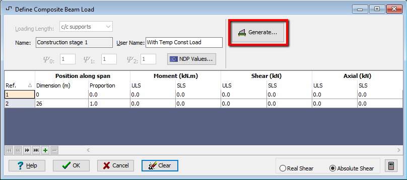
In the User Name field enter “With Temp Const Loads”.
As the beam is simply supported we can use the Generate button to create the bending moments and shears for this case. This will open up the Generate Beam Loads data form, after the display of an information message explaining the limitations of the method.
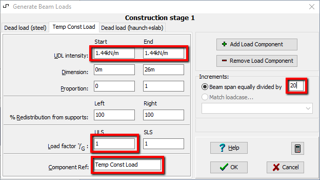
The steel and concrete dead loads have been automatically calculated using the material density and areas defined.
An additional component representing the temporary construction load and water in the wet concrete is added by clicking on the + Add Load Component button. Click on the tab of this additional component and set the Component Ref: field to “Temp Const Load”.
Enter “1.44” into both the Start and End Fields of the UDL Intensity. The load factor for both ULS and SLS can be changed to “1.0”. The ULS load factor for the Steel dead load should be changed to “1.2”.
Set the Beam span equally divided by field to “20”.
Click the ✓ OK button to save this data and close the Generate Beam Loads form.
This will display the resultant moments and shears for this load (noting that the shears are absolute shears, as selected by default on the Define composite Loads data form).
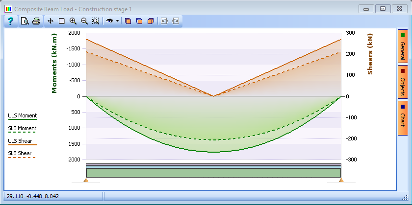
The Define composite Loads form can now be closed with the ✓ OK button
Add a second load effects by using the
 button, in the toolbar of the navigation window, and select Beam Loads | String Course Self Weight.
Use the “Generate” button to create the bending moments and shears for this case. Again, the program automatically calculates the dead load intensity of the edge section.
Set the Beam span equally divided by field to “20” and accept the defaults by clicking ✓ OK.
Close the Define Composite Beam Load form with the ✓ OK button.
Add a third load effects by using the
 button, in the toolbar of the navigation window, and select Beam Loads | Other permanent action. This will be used to represent the removal of the temporary construction loads by applying a negative factor to the load.
Use the Generate button to open the data form then enter “1.44” into the Start and End fields of the UDL intensity. The ULS and SLS Load factors are changed to “-1.0”. The component ref field can be changed to “Temp const load rem” to make it clear what this represents.
Set the Beam span equally divided by field to “20” before clicking ✓ OK to accept the data
In the Define composite Loads form the User Name: field can be changed to “Rem temp const loads” before closing it with the ✓ OK button. (the information form about hogging moments can be accepted).
Add a Forth load effects by using the
 button, in the toolbar of the navigation window, and select Beam Loads | Surfacing.
Use the Generate button to open the data form then enter “3.2” into the Start and End fields of the UDL intensity. The ULS and SLS load factors are left at the default values.
Set the Beam span equally divided by field to “20” before clicking on ✓ OK to accept the data and then closing the Define Composite Beam Load form with the ✓ OK button.
The effects for two live load cases need to be considered:
- Traffic gr1b-gr5 +ve Moment
- Traffic gr1b-gr5 – for Shear design
These are loaded from an ASCII file which has been prepared using a standard text editor. This file has a file extension “.sld” and can be imported by using the “Import loads from SLD file” toolbar button in the navigation window.
This will display a standard file browser allowing the selection of the file called “EU_Composite_Beam_Simple.SLD”. The imported effects can be inspected by selecting the appropriate Beam Load in the navigation tree.
All main loading effects are now defined so any Define Composite Beam Loads form can be closed by clicking ✓ OK.
Setting the Differential Temperature Profile and Shrinkage Strains and Calculating the Primary Stresses
Open the Composite Beam Analysis form by using the
 Analyse toolbar button in the navigation window.
In the Analyse for: field select “Differential temperature primary stress."
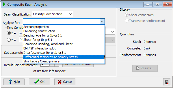
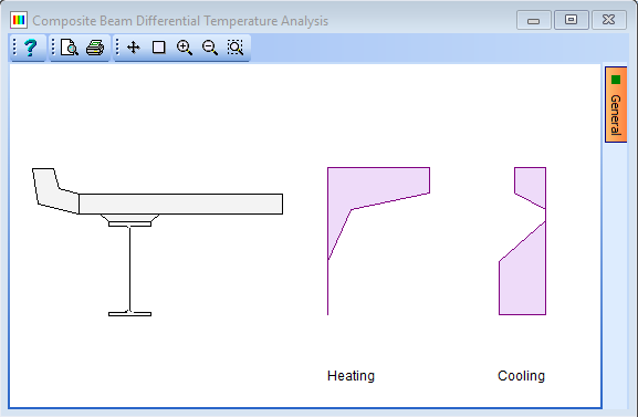
Ensure that the profile Type is set to “EN 1991-1-5 Fig 6.2 Non Linear” and set the field Surfacing to “Surfaced” and the Surfacing Thickness to “0.075”. Also set the Depth of concrete above steel to “0.275” (the slab plus the haunch).
It should be noted that the basic temperature profile for a steel composite design beam assumes that the top of the standard profile is at the top of the slab and that the temperature in the upstand assumes a constant temperature through its depth of that at the top surface of the slab.
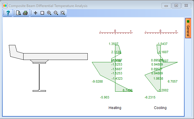
To determine the primary stresses in the section due to differential temperature set the Display: radio button to “Stresses” This will produce a graphical result of the stresses as shown. More details can be found by using the “Detailed Results...” button on the data form.
Close the Differential Temperature Analysis form with the ✓ OK button.
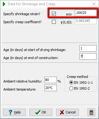
In the Composite Beam Analysis form set the Set parameters for field to “Shrinkage and Creep” which will display the Data for Shrinkage & Creep data form.
The Shrinkage strain should be set to “0.00025” and all the other values left as the default settings (click on the tick box to enable this field).
Close the parameters forms by clicking on ✓ OK.
To determine and display the primary stresses for shrinkage and creep you will need to set the Analyse for field to “Shrinkage / Creep primary” which will display the stresses in the section.
Close the Calculate Shrinkage Stresses form with the ✓ OK button.
Close the Composite Beam Analysis form by clicking on ✓ OK to save this data.
Construction stages
The first design check will be to ensure the ULS capacity of the steel girder, on its own, is greater than the applied load effects during construction.
Open the Composite Beam Analysis form by using the
 Analyse toolbar button in the navigation window and set the Analyse for: field to “BM's during construction”.
Set the Beam Classification field to “Class 1” and select “ULS Persistent/Transient” from the dropdown menu. The calculation is done automatically.
It can be seen from the graphics that the actual mid span construction moment exceeds the bending capacity of this compact section.
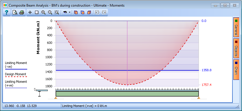
The resulting calculation for this can be seen by first moving the vertical red line on the beam elevation to the mid span point and then clicking on the “Results” button. The vertical red line is moved by using the direction buttons at the end of the field Result Point of Interest.

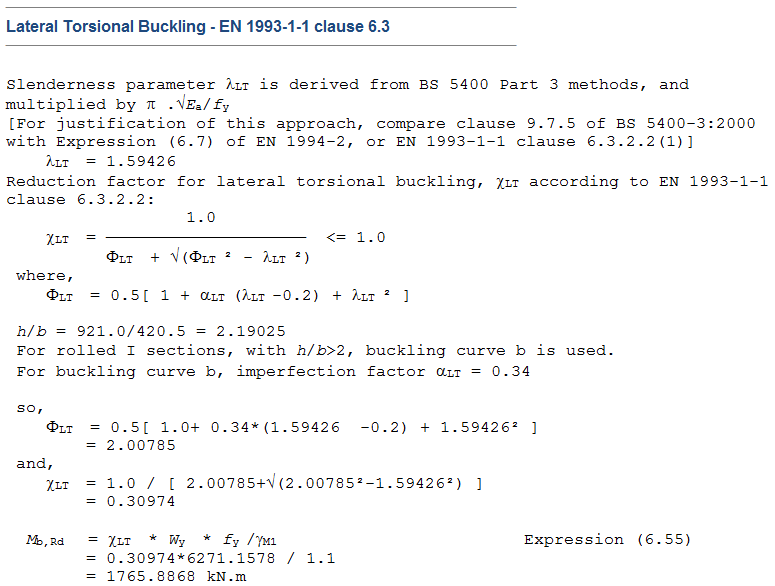
Inspection of the results shows that the slenderness of the girder has reduced the bending capacity of the section by virtue of lateral torsional buckling of the top flange. This could be improved by supplying a torsional restraint to the mid span point of the beam. To do this, change the Set parameter for: to “Bending and Buckling calculations” which displays the Design Data for Bending & Buckling form. Select the checkbox labelled BS 5400 Part 3 at the bottom of the form to open an expanded version of the Buckling data form.
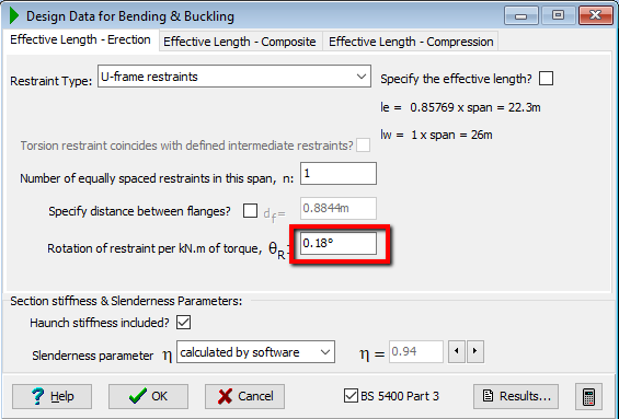
Set the current tab to “Effective Length – Erection” and set the Restraint Type: to “U-frame restraints”. The Number of equally spaced restraints is left as “1” to enable a restraint at mid-span.
The graphics shows that the section is still just failing at mid span.
Reduce the value of _Rotation of restraint per kNm of torque, θr from “1.0” to “0.18”.
We can see that the section then works (note that the BM diagram turns green). This indicates that a transverse restraint is required at mid-span with sufficient bending stiffness so that the restraint end will not rotate by more than 0.18 degrees if a moment of 1.0kNm is applied at the end.
The beam therefore passes this design check.
Close the Design Data for Bending & Buckling form by clicking on the ✓ OK button and then click on the “Results” button on the Composite Beam Analysis form which will open the Results Viewer window displaying the full calculations for the current section. These can be printed if required.
Close the Results Viewer using the Exit button.
Bending Moments under Eurocodes Combination Loading
Only sagging moments need to be considered as the beam is simply supported. Change Analyse for data field to “Bending +ve for gr1b-gr5 ID.1”.
The graphics clearly shows that the design moments are less than the resistance moments along the whole of the beam length.
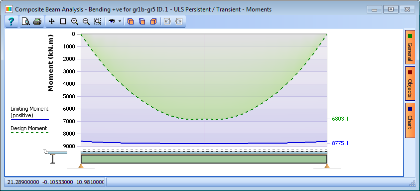
The Display field in the data form can be changed to “Steel stresses” or “Slab stresses” to display the results for these settings.
Now set the Limit State to “SLS Characteristic” and the Display: to “Steel stresses”. Both top and bottom flange design stresses, shown in the graphics, are below the maximum allowable stresses.
The same can be shown for the concrete slab stresses by clicking on the “Slab stresses” radio button (a warning message about adding local to global effects may appear – click ✓ OK on this message). The section therefore passes this design check. Full calculations can be viewed/printed by using the “Results” button as required.
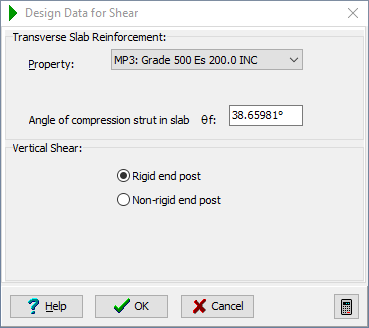
It should be noted that the angle of the compression strut in the shear calculations can be altered by the user in accordance with the code of practice. The parameters affecting these calculations are defined in the Design Data for Shear form which can be displayed by selecting “Shear calculations” in the Set parameters for: field. In this example we will accept the default value. The form is closed using the ✓ OK button.
Verify that temperature stresses are being added by viewing the results.
Vertical Shear under Eurocodes Combination Loading
In the Analyse for: data field, select “Shear for gr1b-gr51” from the dropdown selection; it can be seen that only Ultimate Limit State is available for checking. The graphics clearly shows that the design shears are less than the permissible shear along the whole of the beam length. (Click ✓ OK on the error messages regarding strain compatibility whenever they appear).
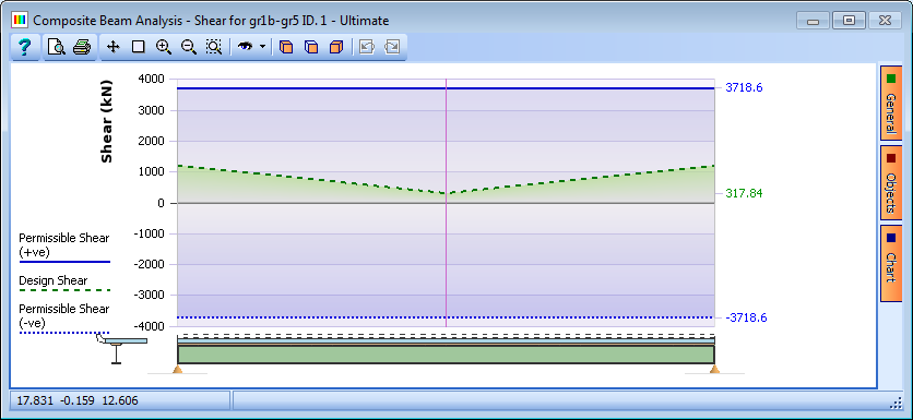
The section therefore passes this design check and full calculations for this can be viewed/printed by using the Results button as before.
Combined Bending and Shear Design Checks
The combined effect of bending and shear are checked using the equations of 6.2.2.4 in EN 1994-2. In the Analyse for: data field, select “Combined Bending, Axial and Shear” from the dropdown selection to display the graphical results.
Both Max Moments with Associated shears and Max Shears with associated moments are checked giving two lines on the diagram.
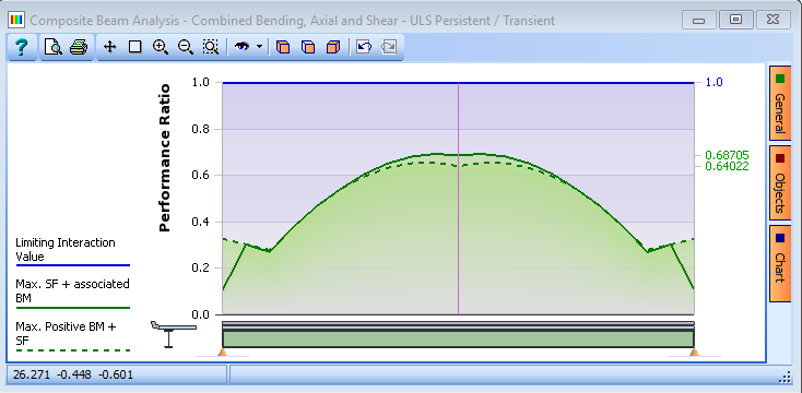
Design for Longitudinal Shear
Longitudinal shear resistance is checked along two planes. The first is the plane of the interface between the steel and concrete and is resisted by shear connectors welded to the top flange and cast into the concrete slab. The second is the vertical plane through the slab adjacent to the edge of the top flange and is resisted by the dowel action of the transverse reinforcement.
Before the design checks can be carried out it is first necessary to specify a default shear connector arrangement and transverse reinforcement. The arrangements and reinforcement quantities can then be adjusted to fit the requirements.
First close the Composite Beam Analysis form by clicking ✓ OK and then open the Define Composite Beam form by selecting “Beam Definition” in the navigation window.
To define the shear connectors, use the drop down list in the Define and locate span features: field to select “Longitudinal Shear Connectors” which will display the Location of Shear Connectors form.
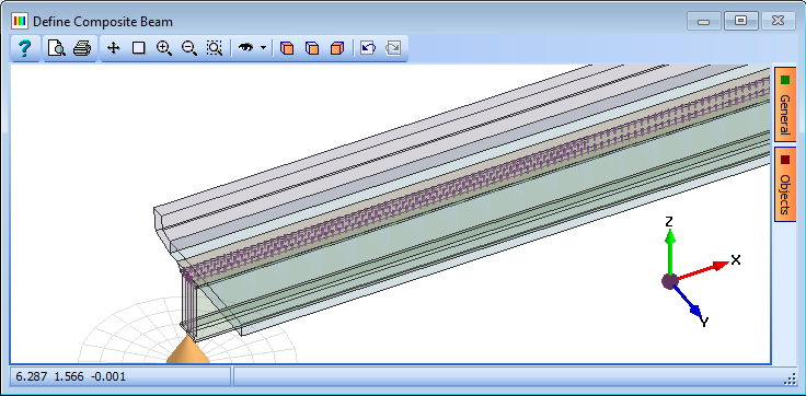
Accept the default arrangement by closing the form by clicking ✓ OK. (Note that the shear connectors are shown in the graphics view – zoom in to see this in greater detail).
The same thing can be done with transverse slab reinforcement before closing the Define Composite Beam form by clicking ✓ OK.
To check the adequacy of the default shear connectors and transverse reinforcement use the
Analyse toolbar button in the navigation window to open the Composite Beam Analysis form. Change Analyse for: to “Interface shear for gr1b-gr5 1” and Display: to “Shear connectors.”
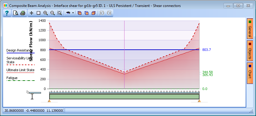
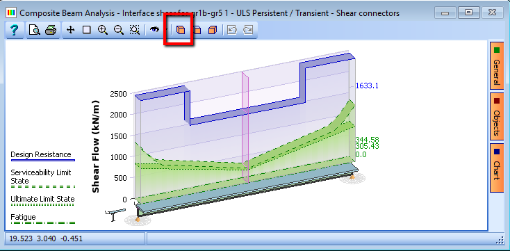
The graphics display shows that the default shear stud type and spacing is not satisfactory at the places of max shear flow. Hence, we would install additional shear links near the ends of the beam in this case.
Now change the Display radio button to Transverse reinforcement and the graphic display now shows that the Design Resistance is not sufficient at the ends of the beam, so the reinforcement needs to be altered.
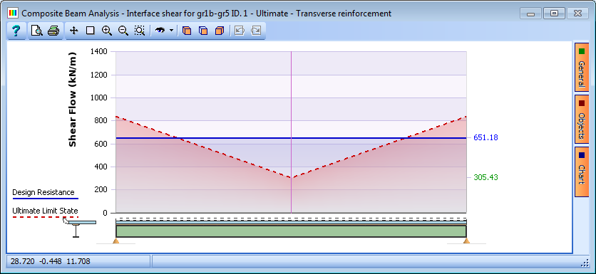
Close the Composite Beam Analysis form by clicking ✓ OK and return to the Location of Shear Connectors form (see step 2... above). The shear connector type and size will remain the same but the spacing can be decreased toward the ends of the beam. Additional rows of data can be added in the form by selecting, in the next available row, the same connector type as the previous lines. This will display a Shear Connector Detail form to define the stud size and strength.
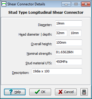
Accept the defaults by clicking ✓ OK then edit the data in the other columns as shown below.
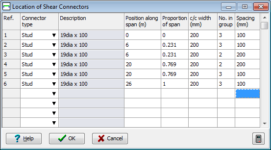
Close the form by clicking ✓ OK. The Transverse Reinforcement in Slab form can be accessed using Define and locate span features. In the case of this example there is no need to alter the bar diameter or spacing of the transverse slab reinforcement because the design resistance has been increased sufficiently by altering the shear studs.
Close all forms and save the changes by clicking ✓ OK.
Open the Composite Beam Analysis form and check that the effects of the changes made to the shear connectors are acceptable.
When the analysis form is open the results graphs can be displayed in a 3D isometric window by clicking on the
 icon on the graphics window. Close the Composite Beam Analysis form with the ✓ OK button.
Click on the File | Save As menu item and save the file as “My EU Example 5_1.sam”.
Close the program.
Summary
In this example we have taken a steel composite beam created in a previous example and applied load to it for a series of design load cases. We have also applied a differential temperature profile and shrinkage strain to the beam, then checked the beam for a series of design criteria.