10.1 Two Span Prestress Beam Deck
Subjects Covered
- Prestressed Precast Beam Structures
Outline
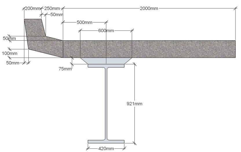
This two span bridge deck is constructed of Y beams (6 in each span with the outer beams being YE beams) acting compositely with a 200mm thick concrete slab.

600mm wide diaphragms are cast to the bottom of the beams along the three lines of support and bearings are placed under the ends of the beams. There is a small 300mm deep upstand at the edge of the slab.
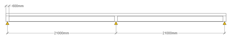
Both spans are 21m from support centre lines which are slightly skewed as shown below.
The slab, diaphragm and upstand are created with grade C32/40 concrete and the prestress beam with grade C50/60 concrete.
Reinforcement is grade B500B with a ductility factor k of 1.15 and an ultimate strain of 0.05. 25mm diameter bars are placed longitudinally at 200mm centres in the top of the slab with 50mm cover. These bars extend 6m into the slab either side of the central support.
The prestressed tendons have a 0.1% proof strength of 1600MPa.
The structure is modelled using a skewed grillage with vertical offsets so that the centroids of each component are at the correct height.
The construction sequence is firstly to place the beams onto supports so that they carry their own weight. The insitu slab (excluding the edge upstand) is then cast for the first 18m of each span, measured from the free ends, leaving a 6m infill over the central row of supports (the end diaphragms are cast as part of stage 1A). The next stage is to cast the 6m infill slab with the central diaphragm, which, when hardened will make the beams continuous over the central supports. Lastly the upstand is cast.
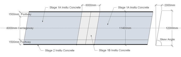
The carriageway is 18m wide with a 1.5m footway on either side.
It is required to design an adequate prestress strand layout with appropriate debond locations to satisfy all execution and persistent design situations for one of the central inner beams. ULS:STR moments and shears should be checked against section resistance, providing shear reinforcement where required. Section stresses under SLS Characteristic combinations of actions should be checked against material limits for all execution stages as well as persistent design situations for normal use.
The actions to consider on the structure are:
- Concrete dead loads assuming 25kN/m³.
- Surfacing loads of 2kN/m² over the carriageway and 3kN/m² over the footways.
- Crash barrier dead loads of 1.3kN/m along the upstands.
- Non linear differential temperature considering a surfacing thickness of 75mm.
- Differential shrinkage assuming that shrinkage drying starts after 2 days and that ambient relative humidity is 80%. Both ambient and curing temperatures are 20 degrees C.
- Traffic actions from Gr1a and Gr5 combinations with a special vehicle of SV80.
All partial factors, combination factors etc should conform to the values in the UK national annex.
Procedure
The general procedure is as follows:
- Create a new project and add titles
- Define the materials needed
- Define 4 prestressed design beams, two edges two inner
- Define a grillage structure and additional design sections
- Create line beam models for the inner line and outer line of beams
- For the linebeam, analyse (automated) for construction, differential temperature and differential shrinkage
- Transfer the results for the two spans into the design beam load tables
- For the refined grillage model, define basic loads and compilations for superimposed dead loads
- Define traffic load patterns for bending and shear using Influence surfaces and load optimisation procedures.
- Transfer the live load effects back to the design beam
- Inspect the results and carry out some design checks