2.6 Composite Section
Subjects Covered
- Multiple components with different materials
- Standard steel library shapes
- Reinforce faces
- Hook Points
Outline
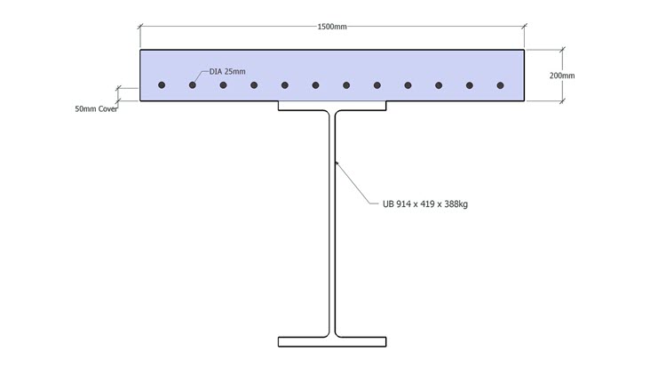
A composite steel girder and concrete slab is shown below. The slab is 200mm thick and the effective width is 1500mm. Reinforcement is placed in the bottom of the slab using 12 no. 25mm diam. Bars, equally spaced with 50mm cover to the bottom face. The steel girder is a standard steel universal beam section classified as 914x419x388. Grade C31/40 concrete is used for the slab and the standard steel and reinforcement materials are applied respectively. The slab is part of a wider continuous slab.
Procedure
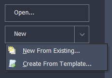
Start the program and select the New drop down button item Create From Template and pick the “EU Section” template.
Use the main menu item File | Titles to set the title as “Composite Steel/concrete Section” with a sub-title of “Example 2.6” and change the job number to 2.6. Click on ✓ OK to close the titles form.
Select Design Section at the bottom of the navigation window and use the + button at the top of the window to create a new section element as a Parametric Shape which will open the Define Section Element form.
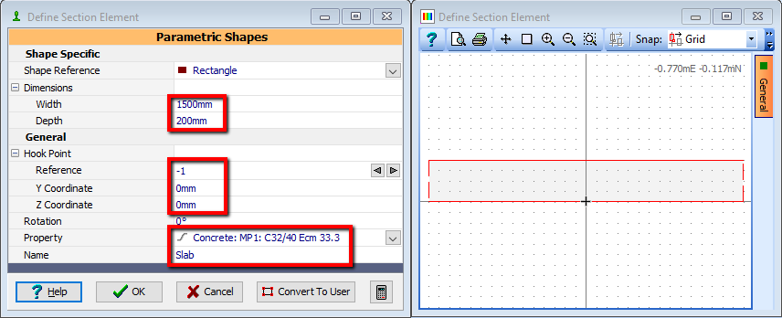
Set the width to be “1500mm” and the height to “200mm”. The slab is to be positioned so that the midpoint of the bottom face is at the origin. This is done by changing the Hook Point Reference to be “-1” and then setting the coordinates to (0, 0).
The two short edges of the slab are identified as continuous faces by clicking once on each (they turn to dashed lines) and the material for the slab is set to grade C32/40 concrete by using the drop down list in the Property field. Change the element Name to “Slab” before closing the form with the ✓ OK button.
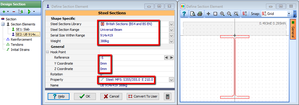
Create a second element to represent the steel girder by using the + button at the top of the navigation window and selecting “Steel Sections”. Use the dropdown list to ensure that the Steel Sections Library is set to “British Sections” and the Steel section range to “Universal Beam”. Then select the Serial size as “914x419” and the weight to “388kg”. Select the “Steel” material from the Property dropdown list.
To locate the top of the flange at the centre of the underside of the slab, change the Hook Point of the steel section to “-5” and set the coordinates to (0, 0).
Close the Define Section Element form by clicking on the ✓ OK button.
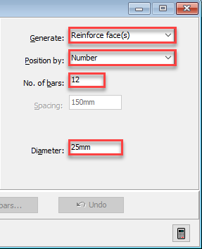
In the Navigation window click on Reinforcement. Ensure the graphics toolbar mode option is set to Insert. Set the Generate field to “Reinforce face(s)”, set the No. of Bars to “12”, set the bar Diameter to be “25mm” and then click on the bottom edge of the slab, which will open a secondary data form.
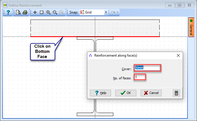
In this form set the cover to be “50mm” and the number of faces to be “1” and then click on ✓ OK to draw the bars.
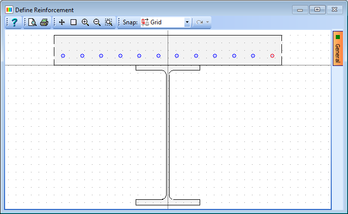
Close the Reinforcement data form using the ✓ OK button.
Use the menu item File | Save as to save the section with a file name “My EU Example 2_6.sam”.
Close the program.
Summary
Sections can be built by combining many different simple components to create more complicated shapes. Special libraries have been built containing the major shapes for steel sections which can be used to build up the section. This covers UK, American, Australian, European and Japanese standard sections.