2.5 Encased Steel Column
Subjects Covered
- Enclosing one section in another, adjusting material properties
- Universal Columns
- Import shape from Autodesk® AutoCAD
- Copying components
Outline
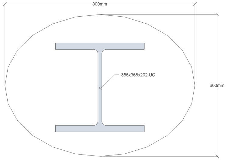
An oval shaped concrete column casing, with major axis 800mm and minor axis 600mm is cast concentrically around a steel Universal Column (356x368x202) as shown below. The concrete is grade C25/30 and the structural steel has a yield strength of 355N/mm² and elastic modulus 210kN/mm². The oval outline has previously been created in AutoCAD and saved in a dxf file. This can be imported into the program before adding the standard steel shape. This shape is added twice, once with void properties (to create a hole in the concrete) and a second time with steel properties.
Procedure
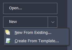
Start the program and select the New drop down button item Create From Template and pick the “EU Section” template.
Use the menu item File | Titles to set the title as “Encased steel section” with a sub-title of “Example 2.5” and change the job number to 2.5. Click on ✓ OK to close the titles form.
Select Materials at the bottom of the navigation window and then open the Property Details for the grade C32/40 concrete by clicking on it in the material list. Change the Characteristic Cube Strength to “30MPa” (30N/mm²) and then click the ✓ OK button on the Define Property Details form to ensure that any changes are saved.
Select Design Section at the bottom of the navigation window and right click anywhere in that window. This will display a pop-up menu from which Import | Import Element and Bars should be selected. This will open a file browser in which the file “EU Example 2_5 Ellipse.dxf” should be located and opened.
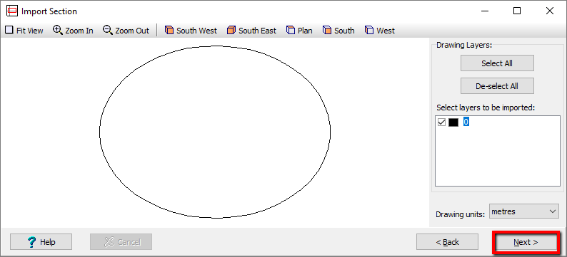
Click the Next > button on the Import Section form which has appeared on the screen. This will display the imported shape in the graphics window and have created a user defined entry in the navigation tree under Section Elements. Click on this element to open the User Defined Section Element form which shows the boundary coordinates and other data for this element.
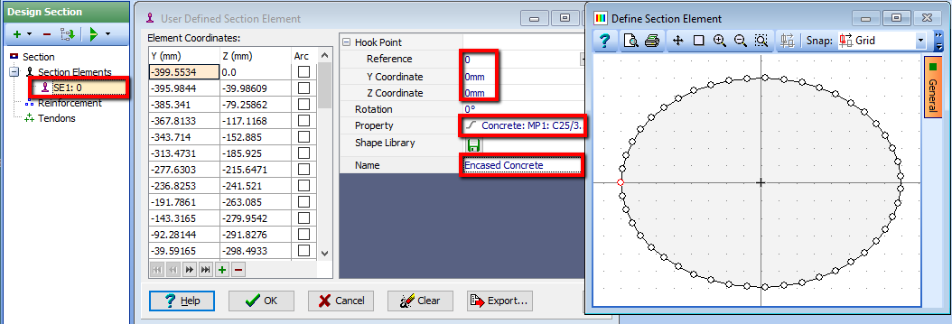
Enter a Name for this component as “Encased Concrete” and set the hook reference number to “0” with coordinates (0,0).
Assign a material property in the Property filed drop down list as the 30N/mm2 (C25/30) concrete.
Add a second Section Element using the + button at the top of the navigation window and select Steel Sections from the available list.
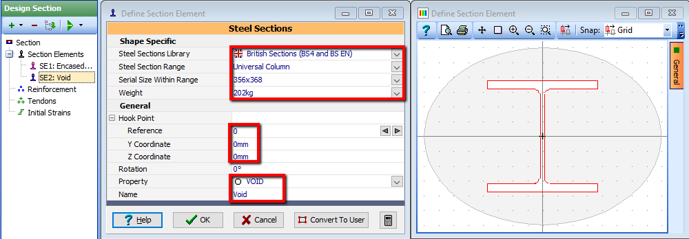
This will open the Define Section Element form in which “British Sections” is chosen and a “Universal Column” is selected from the choice of Steel section range. The serial size is set to “356X368” with a Weight of “202kg”. The hook Reference point is set to “0” with coordinates set to (0, 0). The material Property is left as “VOID” as this is going to form the hole that the steel section will fit into. Change the Name to “Void” then close the Define Section Elements form with the ✓ OK button.
Zoom the image in the graphics window to fit the screen using the “Fit View” toolbar button.

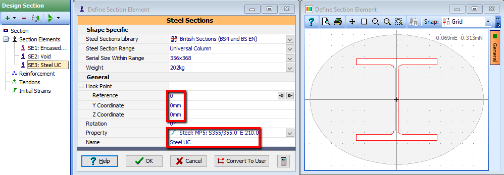
Right mouse click on the “Void” section element in the navigation window and select copy, to create a second instance of this shape, which will open the Define Section Element. Set the Property of this third shape to be that of Steel, the Hook point to 0 with the coordinates at (0,0), and Name to “Steel UC”.
Close the Define SectionElement form using the ✓ OK button and then use the menu item File | Save as to save the section with a file name “My EU Example 2_5.sam”.
Close the program.
Summary
This method is the easiest way of enclosing one shape within another as the “Merge” facility used in Section 2.7 only works when boundaries overlap with each other. This process can be repeated several times to create sections such as a concrete tube enclosed between two concentric steel tubes of different radii.
A second method, which may be necessary in some circumstances, is to create the encasing component as a single component, without a void component, by applying a split between the external and internal surfaces (look at the parametric shape of an annulus as an example). Alternatively the encasement can be made up of a number of separate components, touching at the boundaries (for example, a box section made up from two rectangular webs and two rectangular flanges), although this would not represent the torsion properties correctly.