2.4 Plate Girder
Subjects Covered
- Multiple components
- Joining components
- Copying components
- Rotating components
- Using “Shove” to locate components accurately
- User defined library shapes
Outline
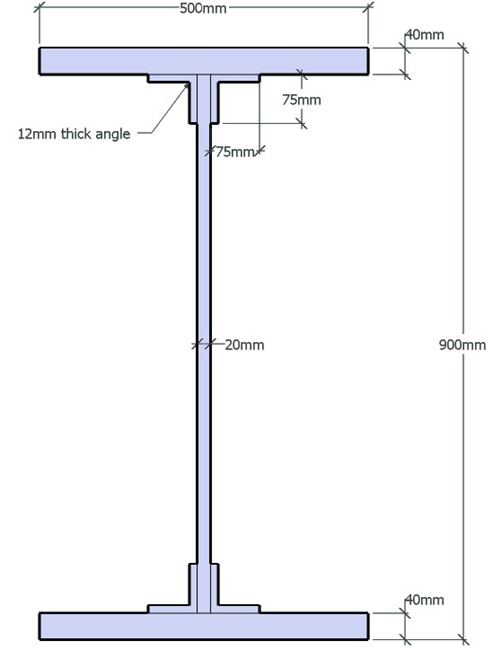
The shape below is created by using a parametric 'I' section and then adding four parametric “Angle” shapes as the cleats. Standard structural steel properties are applied to all components. The section is edited using the join facility to combine the components into one defined shape.
Procedure
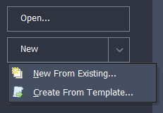
Start the program and select the New drop down button item Create From Template and pick the “EU Section” template.
Use the menu item Design Section | Titles to set the title as “Cleated Plate Girder Section” with a sub-title of “Example 2.4” and change the job number to 2.4. Click on ✓ OK to close the titles form.
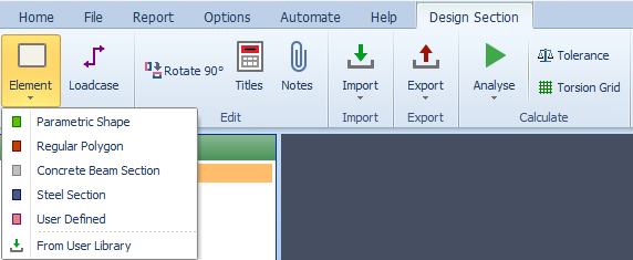
Select Design Section at the bottom of the navigation window and click Add | Element | Parametric Shape in the menu bar to create a new section element as a Parametric Shape which will open the Define Section Element form.
Use the dropdown list to change the shape from “Rectangle” to “I” and set the width of both flanges to “500mm”, the overall height to “900mm”, the thickness of top & bottom flanges to “40mm” and the thickness of the web to “20mm”. The Property should also be set to the structural steel material. Click on ✓ OK to close this form.
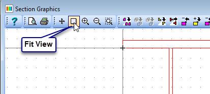
Resize the graphics window to a reasonable size by clicking on the corner of the window and with the mouse button held down, drag to the new position. Zoom the graphics so that the shape fits the new screen size by clicking on the “fit view” button in the toolbar of the graphics window.
Create a second section element as a parametric shape by clicking Add | Element | Parametric Shape in the menu bar. Change the shape from “rectangle” to “L” and set the width and height to “75mm” and the thicknesses of both horizontal and vertical to “12mm”. Also set the material to Structural Steel.
The angle will appear in red with a small cross shown at the reference point. Click once on this cross, releasing the mouse button, and drag the shape to a new location beneath the top flange and to the right of the web, as show below. Place the angle at this location by clicking the left mouse button again.
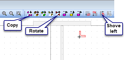
Use the “rotate” edit button to orientate the angle with the arms pointing to the right and vertically down (This could also be achieved by entering the angle in the correct field in the data form).
Now use the “Shove Up” and “Shove Left” edit buttons to locate the angle in its final position.
Now use the “Copy” icon in the graphics toolbar to create a second angle component and repeat 7, 8 and 9 to place it in the top left internal corner.
This can be repeated twice more to place angles into the bottom internal corners such that there are a total of 5 elements in the section.
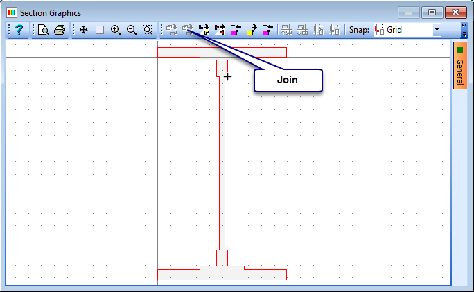
Although this section can be left as five separate components it may sometimes be desirable to join these components into one shape. This is done by selecting one of the angle components and then using the “Join” edit toolbar button to combine it with the component touching or overlapping with it. This is then repeated with the other three angles to give the one “define shape” component. (The user may find that clicking just once on the “Join” button simultaneously joins all of the components together).
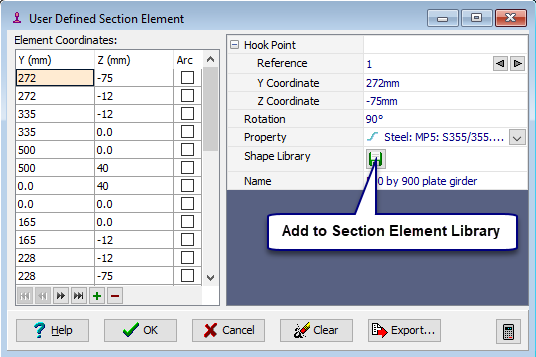
There is now only one element in the defined section which is a “User Defined” general section. Change the name to “500 by 900 plate girder” then click on the button to add it to a library file. This will open a file browser form which will allow you to choose an existing library file, if it exists, or to create a new one. We will create a new one by entering a library file name of “My Useful_Sections.lib” and then clicking on the Save button.
Close the User Defined Section Element data form using the ✓ OK button.
Click on ✓ OK to close the Define Section form.
Use the menu item File | Save As to save the section with a file name “My EU Example 2_4.sam”.
Close the program.
Summary
Sections can be built by combining many different simple components to create more complicated shapes. For composite sections where the components have different material properties then the components will remain as individual entities but if the material is the same they may be joined to form a single shape. This will allow the section to be stored as a single user defined library section.