2.7 Pre-stressed section
Subjects Covered
- Precast concrete beams
- Tendon definition and placement
- Section outline from text file
- Initial Prestress forces
- Arcs
- Merging
- Hook points
Outline
It is required to generate a section of a precast edge beam comprising of a standard YE3 precast beam (Grade C40/50 concrete) and an insitu slab and edge detail (Grade C31/40 concrete) as shown below. The section is created using three components:
- a standard precast section from a built in library,
- a parametric rectangular section for the slab, and
- a general defined shape with specific coordinates for the edge detail.
These sections will overlap so they must be merged to eliminate the duplicated material.
Two rows of tendons are placed in the bottom of the beam (11 in the bottom row and 14 in the second) together with two tendons in the top. The bottom row is placed 60mm from the bottom face of the beam with the end tendons 100mm from the vertical faces. The second row is placed 110mm from the bottom face of the beam with the edge tendons 60mm from the vertical faces. The top two tendons are placed 800mm from the bottom face and 72mm from the edge faces. Each tendon (Grade 1776) consists of one strand of 15.2mm diameter and is initially stressed to 241kN.
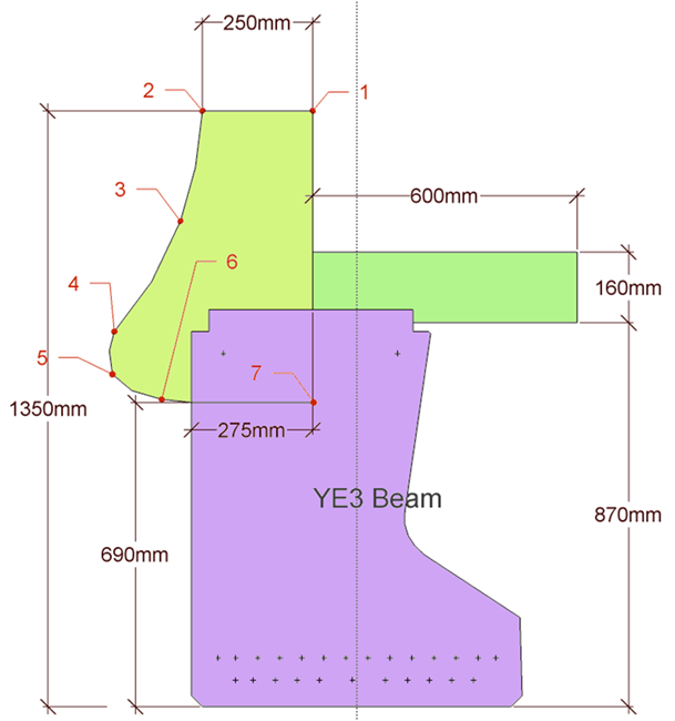
| X | Y | |
|---|---|---|
| 1 | -100 | 1350 |
| 2 | -350 | 1350 |
| 3 | -400 | 1100 |
| 4 | -550 | 850 |
| 5 | -554 | 753 |
| 6 | -450 | 690 |
| 7 | -100 | 690 |
| 8 | -100 | 1350 |
Procedure
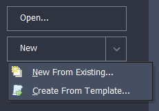
Start the program and select the New drop down button item Create From Template and pick the “EU Section” template.
Use the main menu item File |Titles... to set the title to be “Prestressed Edge Section”, set the sub-title to “Example 2.7” and change the job number to 2.7. Click on ✓ OK to close the titles form.
Select Materials at the bottom of the navigation window and delete the structural steel by selecting the material in the list and using the right mouse button menu select the Delete option.
Open the data form for the Prestress Steel material and set the Characteristic Tensile Strength to 1776MPa (1776N/mm²). Click ✓ OK on the warning message. (This gives a force of 241kN when 75% is applied to a 15.2mm diameter strand).
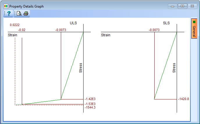
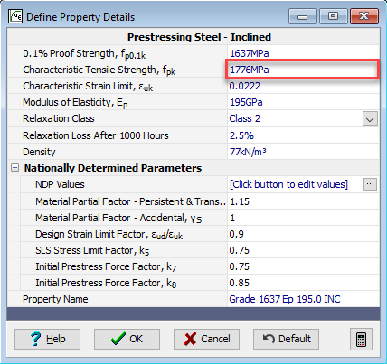
Click the ✓ OK button on both the Define Property Details form to ensure that any changes are saved.
Select Design Section at the bottom of the navigation window.
Use the + button at the top of the navigation window to create a New Section with this first element being defined by a “Concrete beam Section”. This will display a data form (with graphic showing a standard bridge beam). Select “British Sections” from the Concrete Beam Library drop down list and set Concrete beam range to be “YE beam” and the Shape no. to “YE3”.
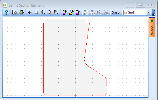
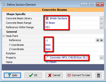
Assign grade C40/50 concrete to this component by using the drop down selection of the Property field and manipulate the positions of the components so that the origin is at the midpoint of the bottom face of the beam. This is done by setting the Hook Reference point to “-1” and setting the coordinates to (0, 0). Close this form using the ✓ OK button and select No when prompted so that default tendons are not automatically defined.
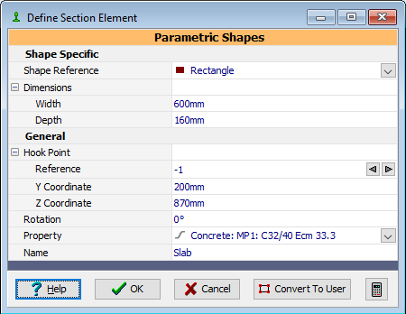
Use the + button at the top of the navigation window to create a second section element as a rectangular parametric shape with a width of “600mm” and a depth of “160mm”. Assign grade C31/40 concrete to this component and set the Name to “Slab”.
Now the insitu slab can be positioned by also setting the Hook point to -1 and the coordinates to (200,870) (allowing 20mm for permanent formwork above the rebate).
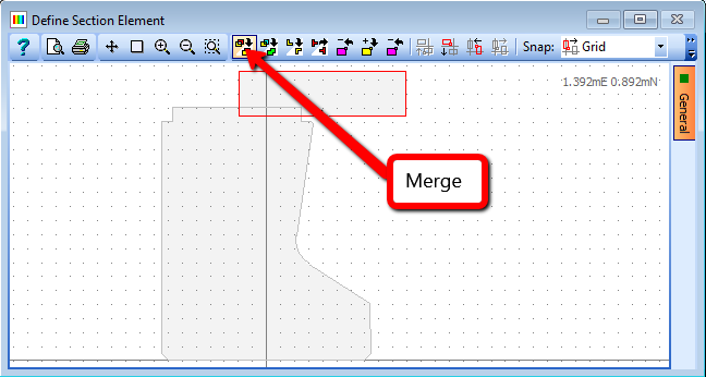
The two components overlap, so, to cut out the insitu slab around the beam click on the Merge button in the graphics widow toolbar. Then close the Define Section Element form with the ✓ OK button.
The insitu edge detail now needs to be defined. Create a third component, using the + button at the top of the navigation window and select Section Element - User Defined.... The coordinates, as defined in the table in the introduction, can be entered by either typing the coordinates directly into the shape coordinates table (using the + button to add a row), or by entering the coordinates into a text file such as notepad, copying them to the clipboard
and then using the right mouse button menu option in the coordinate table, pasting them in. Set the section Name to “Edge Detail”. A more accurate shape can be given by fitting arcs where appropriate. Tick the arc box in rows 3 & 5. Again the edge section overlaps the precast beam element so cut out the edge section around the beam by clicking on the Merge button in the graphics widow toolbar and then assign grade C32/40 concrete to this component before closing the form with the ✓ OK button.
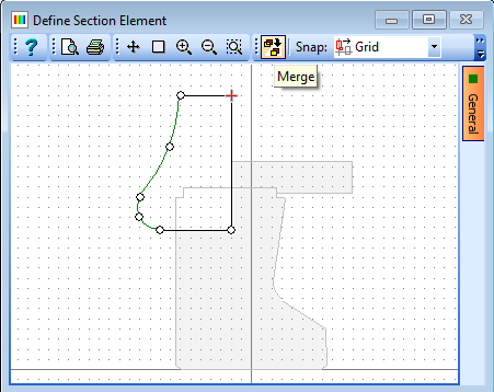
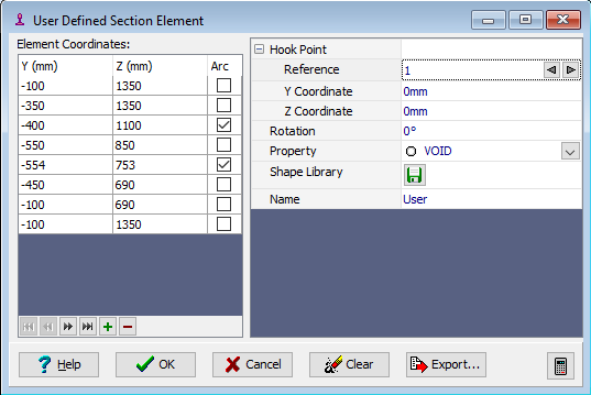
To define the tendons select “Tendons” in the navigation tree which will open up the Define Tendons data form.
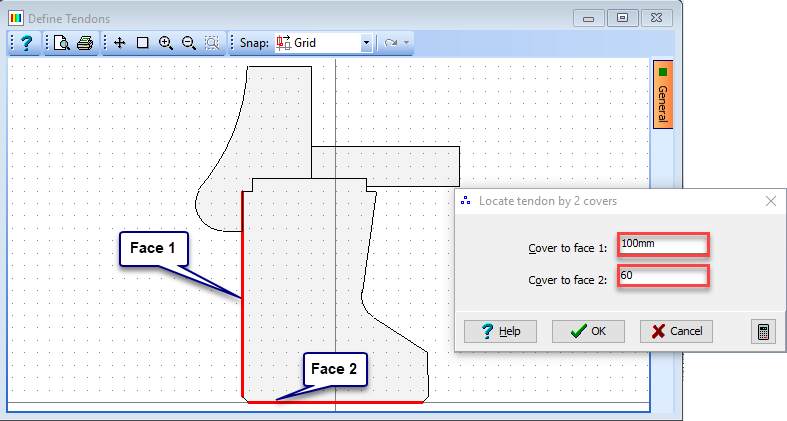
Select “1 tendon by 2 covers” from the dropdown list in the Generate field and set the area of strand to “181mm²” (the area of a 15.2mm diameter strand). In the graphics window click on the left vertical face of the precast beam (becomes bold) and then on the bottom face which displays a secondary form. Set the Cover to face 1 to “100mm” and Cover to face 2 to “60mm”. Click ✓ OK on the Locate Tendon by 2 covers form. Notice that the force in the tendon is 241kN (but this could be changed as necessary). Repeat this for the bottom right corner of the beam. Repeat on the bottom right corner with covers to face 1 and 2 “6mm” and “110mm” respectively and then again on the bottom left.
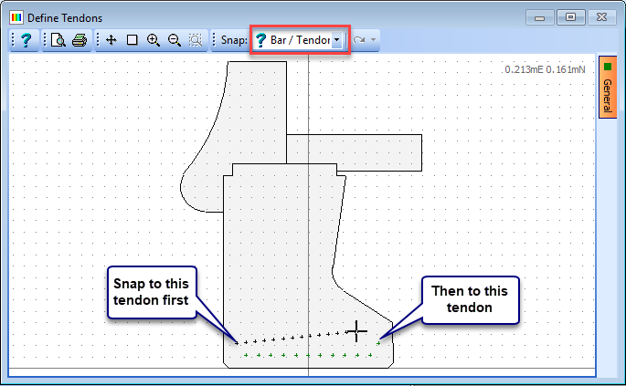
Select Draw tendons from the dropdown list in the Generate field and change the snap option in the graphics window toolbar to “Bar/Tendon”. Ensure the mode option is set to Insert. Set Position By to “Number” and No. of tendons to “11”. Now click on the bottom left hand tendon in the graphics window and then again on the bottom right (generating 11 extra tendons with superimposed tendons in the corners). Repeat this for the second row but setting the number of tendons to 14.
The top two tendons are created by using “1 tendon by 2 covers” option and selecting the vertical and bottom edges with covers of “72mm” and “800mm” for both corners.
Close the Define Tendons form using the ✓ OK button. An information message is displayed informing that superimposed tendons have been automatically removed. Click OK on this message.
Use the main menu item File | Save As to save the data file as “My EU Example 2_7.sam”.
Close the program.
Summary
This section is now ready for section property calculations and stress analysis. The example shows the build up of components, using merge, arc, and hook point facilities as well as illustrating the use of standard library shapes. The edge detail illustrates the ability to cut and paste geometry from a spread sheet or text file. Inserting tendons demonstrated that a tendon could be placed with respect to two faces (which don't have to be contiguous). The default tendon force is calculated from the characteristic strength, the initial percentage and the tendon area, although this will generally be adjusted to take care of losses.