2.1 Simple Edge Section
Subjects Covered
- Titles
- Material property changes
- Section Definition
- Parametric Shapes
- Define shapes
- Inserting points
- Arcs
Outline
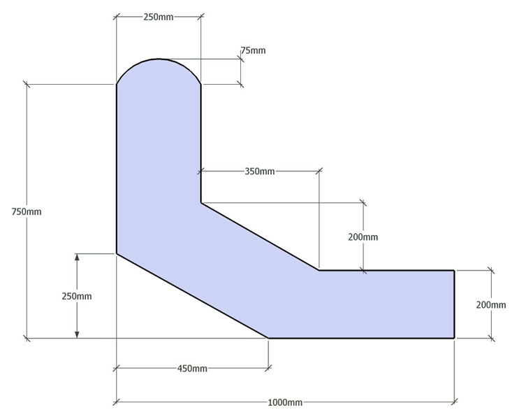
The shape below is created by using a parametric 'L' section and then modifying by inserting points, changing vertex coordinates and changing segments to arcs. Grade C31/40 concrete is assigned to the section.
Procedure
Start the program and select the New drop down button item Create From Template and pick the “EU Section” template.
Use the main menu item File | Titles to set the title as “Grillage Edge Section” with a sub-title of “Example 2.1”. Click on ✓ OK to close the Titles form.
At the bottom of the navigation window on the left side, select Materials and then delete the structural steel (Redundant property) by selecting this material from the navigation tree and then use the right mouse button menu to select "Delete".
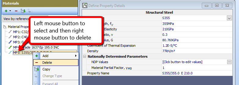
Repeat this for the Prestressing Steel.
Now select Design Section at the bottom of the navigation window and use the + button at the top of the window to create a new section element as a Parametric Shape.
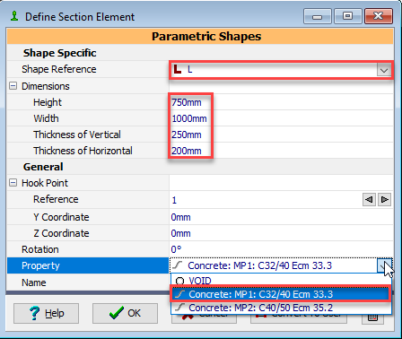
This will display a form (with graphic) showing a rectangular shape. Use the dropdown list to change the shape from “rectangle” to “L” and set the width to “1000mm”, the height to “750mm”, the thickness of horizontal to “200mm” and vertical to “250mm”. Also set the material property to grade C32/40 concrete by selecting the appropriate property from the drop down list.
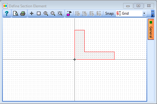
Click on the Convert to User button to change the “Parametric Shape” into a “Define Shape” which will change the form and graphic to display all the vertices and coordinates. We will now add some additional points and edit the coordinates to provide the correct shape boundary.
Click on the second point in the vertices (Y) list and notice that the circle around the point at the bottom right of the “L” has turned red. This is the current point. Select the + button to insert a point midway along the bottom edge of the “L”.
Now click on the fifth point in the vertices list and use the + button to add a point midway along the top of the bottom flange.
Now click on the eighth point in the vertices list and use the + button to add a point midway along the top edge of the vertical.
Change the coordinates in the table to the following:
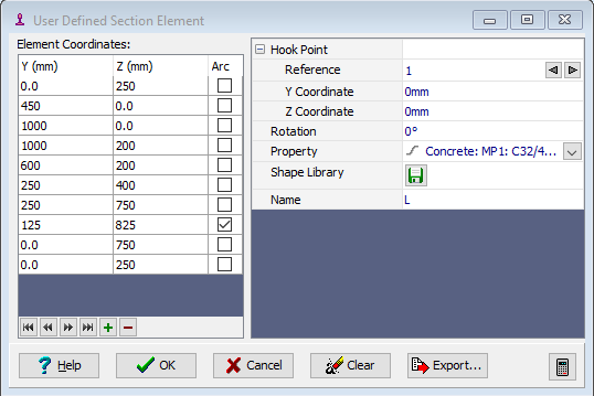
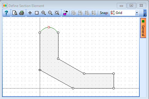
Click on the Arc tick box for the point (as shown) at the centre of the top of the vertical to create the curve on the top. Change the Name field to “Edge Section”.
Click on ✓ OK to close the User Defined Section Element form.
Use the main menu item File | Save as to save the section with a file name “My EU Example 2_1.sam”.
Close the program
Summary
Section shapes can be created in a number of ways. There are many predefined parametric shapes and standard beams stored in the program library, which can be used unaltered. These can be converted to a general defined shape and modified.
This example shows how to do this and how to assign a particular material to a section component.