Photos, Issues, and Measurement
Feature markups either represent or link to other tools by allowing you to create an issue, or add an existing photo to your sheet. The measurement markup allows you to calibrate a sheet and create measurements for lines, rectangles, and free-form shapes.
Create Issues in the Viewer
You can create issues and place them on your sheet.
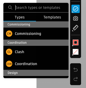
Select the issues markup tool
 from the toolbar
Select from the issue Types or Templates.
- Types are preconfigured or created in the Types settings
- Templates have an associated type and can contain prepopulated information to make creating issues faster. Templates are created in the Templates settings
Click the sheet to create an issue markup
 which is automatically published
 Edit the desired fields in the panel
Note: If there is at least one empty required field in the chosen type or template, the issue will be created in the Draft status. You cannot change the status until all required fields are complete. Required fields are marked with an asterisk. Project administrators set fields as required in the Statuses settings. You can find all your draft issues by filtering the Issues log.Tip: With an issue selected, you can also hold and drag the issue markup to reposition it.Click the close icon
 in the panel to return to the sheet
You can view and navigate through all the issues on your sheet using the issues list view.
Add a Photo Markup in the Viewer
Reference an existing or new photo by adding a photo markup.
- Select the photos markup tool
 from the toolbar
 - Click the sheet to create a photo markup

- Click Add in the Photo References panel
- Select existing photos or click Upload new
- Click Add
- Click Publish
Measurement Tool
To make plans, quick decisions, and understand quantity, accurate measurement is key to members. The measurement tool is used first to calibrate a PDF file to set up a scale and associated ratio measurement. Once calibration is published, members can then create measurements.
Calibrate Document
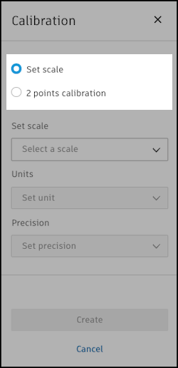
Select the measurement tool
 from the toolbar.
Click
 .
.You can select to either Set scale or make a 2 points calibration.
Set scale
You can select the desired scale for the whole drawing file. This can match the actual scale detailed on the drawing file.
Select Set scale.
For example, your drawing might have the following scale
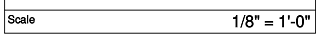 . You can therefore set the scale for any measurements to
 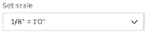 .
.Enter your options in the panel:
- Set scale: Select the desired scale.
- Units: Select your preferred unit of measurement.
- Precision: Set the precision of the calibration used for the measurements that you create.
2 points calibration
You can define two points to use as the basis of your calibration.
Select 2 points calibration.
Select two points to create a line to use for your calibration.
Enter your options in the panel:
- Set size: Add a size that represents the scale of your line in real life (For example, a 1-cm calibration line could represent 5 m on site).
- Units: Select your preferred unit of measurement.
- Precision: Set the precision of the calibration used for the measurements that you create.
Click Create.
You can also remove the calibration. This will permanently remove the calibration and affect any existing measurements that have been made.
Now that calibration has been created and published, members can create a measurement based on that calibration.
Add a Measurement
Select the desired measurement markup tool:
 Straight Line
 Polyline
 Freeform Line
 Rectangular Area
 Polygon Area
 Freeform Area
Draw your desired measurement.
Note: A number will appear in lines or freeform markups based on the actual length of the line or free-form and the calibration you have previously set. For rectangles, the number represents the area of the rectangle.Edit and style the markup using the available options in the Details tab and add any reference links in the Links tab.
Click Publish.