Commands in Autodesk Inventor.
Connectors
A connector appears as a feature in a component document. In the model browser, its icon is
 .
.
In the graphics window, the connector displays as a yellow sphere with an axis triad (similar to a User Coordinate System ).

- The Z axis of the connector is the joining direction. If the joint has a Gap value, the offset is along this direction.
- The X axis is the alignment direction.
Commands

 Infer Connectors
The Infer Connectors command infers connectors from an assembly joint.
One connector is created for each of the joined component documents. If a connector with the same name as the joint exists in the document, the connector is edited rather than created.
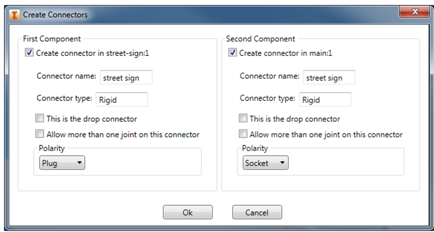
Create Connectors dialog box
The component names display in the message, Create connector in... If you want to create (or edit) a connector in only one of the components, deselect the option for the other component. Avoid creating connectors in the base assembly. Reuse an existing connector instead of creating a new one.

- Connector name
- By default, the connector name is the same as the joint name, but you can change it.
- Drop connector
- When you drop an accessory onto the base assembly design in Configurator 360, the system tries to find a match for the drop connector on the component the accessory was dropped on. If the system finds a matching connector, it automatically creates a connection. This generally only applies to a Plug connector.
- Allow more than one joint on this connector:
- Select this checkbox to allow more than one component to connect to the same connector. This applies only to a Socket connector.
- Polarity:
- Select Plug, Socket, or Neutral. To create a joint between two connectors, their polarities must match.
- Possible matches:
- Plug matches Socket and Neutral
- Socket matches Plug and Neutral
- Neutral matches Plug, Socket, and Neutral
By default, the first component (moving component, accessory) is a Plug and the second component (stationary component within the base assembly, or already-placed assembly) is a Socket.
 Edit Connector
A connector shows up as a feature in the component document. Right-click on the feature in the model browser and use this command to edit the same properties available in the Infer Connectors dialog box.
 Connect
Connect is used to verify connector operations in Inventor. Connect creates a joint between two components that have matching connectors. In the dialog box, all available connectors display and are selectable. Once you select one, the selection disables all that are incompatible.
 Update Connectors
Although the connector is associative to the geometry underlying the joint it was created on, the graphics are not. If you modify the geometry, the connector graphics position becomes out of date. Use the Update Connectors command to update the graphics. In an assembly, this operates on all component documents.
 Connector Visibility
Connector Visibility is a drop-down command with checkboxes to Show or Hide the connector graphics. In an assembly, this operates on all component documents.
Limitations
- Connectors cannot be inferred from a joint with an origin defined as Between Two Faces.
- On Inventor 2014 and 2015, connectors cannot be inferred from a joint defined with an Offset Origin.
- Infer connectors from joints that have range of motion limits, but the limits do not take effect on Configurator 360.