- IDW or Inventor DWG
- All IDW or Inventor DWG files included in an IAM-type design are available for download. If there are multiple files, they are packaged in a zip file. The drawings are searched within the folder hierarchy (for non-ETO assemblies).
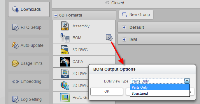
- BOM Output Options
- Select the appropriate BOM view: Parts Only or Structured.

- RFA
- Export includes all model properties (with or without values) including Material name and Density (g/cm^3), Mass properties (Mass, Surface Area, Volume), and using document settings for linear and mass units.
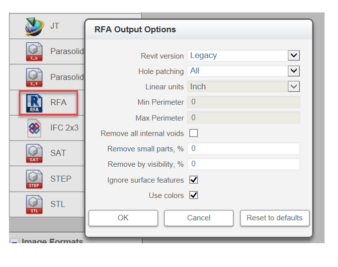
- RFA Settings
-

- Specify the width and height of your image pixels. The default size of your image is 1024 x 768.
-
RFA Output OptionsNote: These fields also appear in the IFC 2x3 Output Options settings.

-
- Revit version: Legacy is the previous version of Revit, providing compatibility with Revit users who have not upgraded to the latest version of Revit. This option is supported for RFA output only.
- Hole patching: (All / None / Range) Controls how Configurator 360 patches up holes and pockets in your model. Select Range to patch holes within the range of perimeters chosen. Perimeter values do not apply if All or None is selected.
- Min Perimeter: Select the minimum Perimeter to apply to your Range.
- Max Perimeter: Select the maximum Perimeter to apply to your Range.
- Remove all internal voids: Select this option to fill all internal void shells in the model.
- Remove small parts, %: Remove small or hidden parts from the model.
- Remove by visibility, %: Set the percentage visible. 100% shows all components that are considered visible. 0% shows only the most visible component.
- Ignore surface features: If you select this option, surface features do not affect visibility detection. For example, if a domed surface is covering two components, the two components are considered visible because the domed surface is ignored. If you leave this option blank, surface features participate in visibility detection and can hide geometry. In the domed surface example, the components would not be visible because surfaces are considered the same as solids.
Note: To control options for DWG (AutoCAD) or DXF outputs, you can upload an
OptionsDWG.ini and/or
OptionsDXF.ini file along with your model files. Configurator 360 uses this file when generating the corresponding formats.