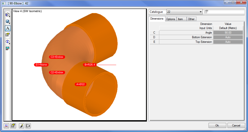
The CAD Takeoff dialog (also referred to as the Takeoff dialog) is used to configure items ready to be inserted into a drawing. This dialog automatically displays as part of the process for inserting an item into a drawing, when it is the first item being placed into the model.
The Takeoff dialog does not display when the item has the Certified flag option enabled from its Items Properties. This means the item will use the carry-over values of the previous item and not request a change to the item's properties.
The CAD Takeoff dialog has the following tabs for editing (when allowed) or viewing detail: Dimensions, Options, Items and Other. Whether the fields in the tabs are available for edit depends on the following:
- For Product Listed items assigned ADSK Ownership, the user would not have the permissions to edit any of the Item Properties. Manufacturers (non-generic) content available from within the software belongs to Autodesk, and therefore, any changes would need to be highlighted to Content Team. Some content is restricted and can only be used for drawing or takeoff (is non-editable) and based on manufacturers true dimensional data.
- For template items (for example, rectangular fittings), certain dimensions may have locks or calculated fields (for example, calculated dimensions). These can be changed by editing the lock icon, or changing the calculated dimension rules. You can change the default or current settings by right-clicking on the item in the Service Pallet, and clicking Edit. Doing this displays the Takeoff dialog for edit.
View Toolbar
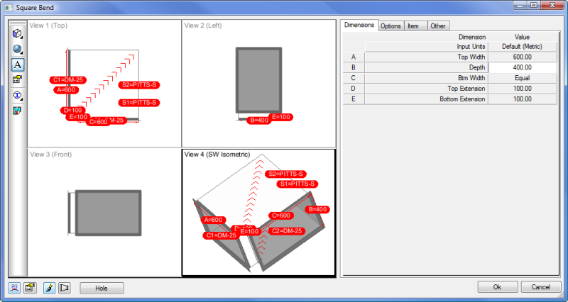
The Takeoff view inside the Takeoff dialog comprises of a custom selection of up to 4 views. Using the toolbar that is docked on the left, you can access options to change the way this view area has been preset.
 Changes the number of views and prompts for a number 1-4.
 Change the view perspective of the highlighted segment (Top, Bottom, Left, Right, Isometric, and SW Isometric).
 Toggle between shaded or 2D wire frame amongst others.
 Display annotation for the selected view (notice there is a selection around the current view (View 4 (SW Isometric as shown below).
 Go directly to the View Settings, which controls the views Takeoff style for font and annotation defaults or preferences to color etc.
 Toggle on or off the textures used via the Duct Facing field.
Lower Toolbar
You can quickly access various options using the toolbar buttons that are located on the lower right corner of the Takeoff dialog. These buttons are for accessing the database, customising the CAD Takeoff view, the ability to redraw after altering dimensions, viewing part developments, and the option to add manual holes to part developments.
 Accesses the global database which contains specifications and connectors amongst other options.
 Edit the Item tab view to add/remove fields when using the CAD Takeoff dialog. For example you can add in a Duct Facing entry for texture application, which will then be visible each time the CAD Takeoff view is used.
 Redraws the item in each of the views after any dimensional changes.
 View the items developments for area or weight references and X/Y blank sizes.
 Gives the opportunity to add multiple holes on either of the faces. New parameters will become available in the Dimension/Options tabs to specify size or change offset values. These hole(s) will become visible in the views after application, and they also alter developments by creating inner islands.