Once you have created a new service to be used by Autodesk Fabrication products, the next step is to configure a variety of options on that new service. The steps below describe how to configure these options on the new service.
To configure a new service:
- Display the new service to configure by clicking Database
 Takeoff
 Services, and selecting the desired service in the Service pull-down field.
- Specify the following options:
- Default Shape: This is typically set to Round for a pipework service. This default shape setting is needed for using Design Line.
- Flow Direction: This is typically set to Not Set for mechanical systems, and to Extract for drainage systems.
- Ignore Fitting Angle Tolerance: When selected, the Angle Tolerance setting defined within each item's Options setting is not used to accommodate for variation in deflection due to slope or misalignments.
- On the Service Types tab, click New Entry.
The Define Service Entry dialog displays. This specifies the service type and layer information.
- Click the Button Mappings tab.
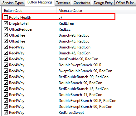
This tab lets you specify the Button Code and Alternate Code, which defines the content layout when drawing a Design Line.
- Click New Entry.
The Define Button Mapping dialog displays.
- On the Define Button Mapping dialog, select a Button Code from the drop-down list (for example, select OpenEnd).
- Place the cursor inside the Can be Made By Using Alternates pane to display the list of alternate codes that can be selected.
- Select an appropriate alternate code (for example, select CapEnd), and then click OK.
- Repeat these steps to add all the button code and alternate code needed in the Button Mappings tab.
Below are examples of button mappings of mechanical and drainage systems.
Mechanical System Button Mappings Drainage System Button Mappings 

- Click the Constraints tab.
The sizes of all items in this service will be added here. The constraints will define the size and color of Design Lines.
- Click New Entry, and on the Define Constraint dialog, specify the following:
- Name: Enter a name for this constraint. The name is typically the size of item.
- Line Thickness: Specify a thickness of the Design Line. Usually the size of the thickness is half of the diameter size.
- Colour: Specify the colour of the Design Line.
- Shape: Specify the shape used to draw this item when using Design Line. For pipework, this is typically set to Round.
- On the Define Constraint dialog, click the New (Add Restriction) button.
- For the Type of Restriction to Add, select Diameter (inch), then click OK.
- Specify appropriate values for Preferred, Min and Max, then click OK.
These values must be appropriate for the diameter of the item.
- Click OK and notice that one size has been added to the Constraints tab.
- Repeat the previous steps to add all the necessary sizes to the Constraints tab, then click OK.
- Click the Design Entry tab, and click the Design Annotation Settings button to display the Design Annotation Settings dialog.
This dialog lets you specify a variety of annotation display settings for Design Line.
- Make sure the Lines tab is selected.
- In the Display column, set each Line Attribute to Hide or Show as appropriate, and then click OK.
For example, attributes that are set to Hide are not displayed when this service is drawn using Design Line.
- Click the Nodes tab and configure the Line Attributes as appropriate. Click OK to close the Design Annotation Settings dialog.