In CADmep, the Levels command is used to display the height of the duct from the level (Z=0) or a datum point set up in the Level Text area of the main database. Levels can be displayed with reference to the top of the duct (T.O.D.) or the bottom of the duct (B.O.D.) or both.
The Level Text options are specified in the database as follows:
- Click
 Edit Main Database
 Takeoff tab
CAD Settings
Annotation tab.
Takeoff tab
CAD Settings
Annotation tab.
- Scroll down to Level Text options.
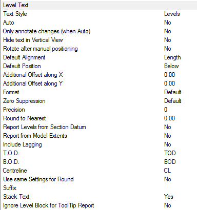
- The Style box is used to specify the AutoCAD Text Style to be used. If the Text Style Levels is not present, then Standard is used by default.
- Text Style: Text properties taken from Style named here, if the style dose not exist "Standard" is used. Height, Width, Font etc are defaulted from style. If only displaying in paper, height should be size required for plotting.
- Auto: Automatically applies the Numbers label to each item drawn.
- Only annotate changes (when Auto): Only applies a Size label, when the item has changed Size or cross section from the previous item connected from. Note : Option Auto must be set to Yes to utilise the Only annotate changes.
- Hide text in Vertical View: Hides stacked annotation in Vertical views, e.g. for a riser viewed in Plan would only display the base items' annotation.
- Rotate after manual positioning: An option to rotate the Size label; useful if the Label alignments option do not allow desired Alignment because of UCS or Item rotation.
- Default Alignment: Sets the annotations' alignment: View, Length or Connector (default Length).
- Default Position: Sets the annotations' alignment: Below, Middle or Above (default Below).
- Additional Offset(s) X, Y: Allows an additional offsets from the default Position.
- Format: If the Format option is set to value greater the 1, then the above settings are over-ridden as follows:
- 1: Scientific 1.55E+01
- 2: Decimal 15.50
- 3: Engineering 1'-3.50"
- 4: Architectural 1'-3 1/2"
- 5: Fractional 15 1/2"
- Zero Suppression:
- Default
- Suppresses zero feet and precisely zero inches
- Includes zero feet and precisely zero inches
- Includes zero feet and suppresses zero inches
- Includes zero inches and suppresses zero feet
- Suppresses leading zeros (Decimal)
- Suppresses trailing zeros (Decimal)
- Suppresses leading and trailing zeros (Decimal)
- Precision: If set to -1, precision is controlled by the AutoCAD - Format Units setting. If set to 0-7, precision is controlled by CADmep (zero to seven decimal places)
- 0
- 0.1
- 0.12
- 0.123
- 0.1234
- 0.12345
- 0.123456
- 0.1234567
- 0.12345678
- Round to Nearest: When this option is selected, values round to the nearest value.
- Report Levels from Section Datum: Forces the levels command to use the Elevation Datum value from the https://beehive.autodesk.com/community/service/rest/cloudhelp/resource/cloudhelpchannel/guidcrossbook/?p=FABRICATION&l=ENU&accessmode=live&guid=GUID-ABD77BCF-F9C0-4B5E-872C-C3B97B1B6659 as a datum, rather than the items physical position in the drawing i.e. duct located at zero can report a level of 10m.
- Report from Model Extents: Levels report from the items' Model Extents.
- Include Lagging: Levels reported include an items external lagging.
- T.O.D.: Abbreviation displayed for the Top Of Duct value.
-
B.O.D.: Abbreviation displayed for the Bottom Of Duct value.
Note: Leaving the T.O.D. or B.O.D. fields empty will stop any Levels information displaying.
- Centerline: Abbreviation displayed for the Center Line value (Round only).
- Use same Settings for Round: Forces Round Levels to be taken from the Top/Bottom of duct rather than the default setting (Center Line.)
- Suffix: Option to include a Levels suffix.
- Stack Text: Levels text stacks vertically rather than horizontally.
- Ignore Level Block for ToolTip Report: Enables or disables the tooltip reporting as per the Level Block attributes (if in use).
Using the Levels command
To use the Levels command:
- Click the Levels icon
 .
.
- Select the Items to displayed the levels. This can be done using any of AutoCAD normal selection commands.
- Right-click to execute the command.
The Levels text should now be displayed. The Levels text can be moved and rotated using the AutoCAD grips or using the CADmep Move Text
 and Rotate Text
 commands.
Additional Notes
-
Selecting and reapplying any of the CADmep label commands will toggle the label on or off.
-
If the label is toggled off then on again it will remember its original position and rotation.
-
If no Annotation is displayed check that the AutoCAD Text Style has been setup correctly.
-
You can also configure Level text options in
Database
Takeoff tab
Services
CAD Types
Level Text.