The CAD Types options can be used as part of the services layering system. It allows the user to break down the components which make up an item and place them onto individual layers. For example, annotation components such as duct sizes, numbers etc. can be placed on their own layers, allowing them to be switched on and off independently of each other. Alternatively, all the annotation can be placed on one layer for easy manipulation. A common practice is to combine the CAD Type with the service type, and separate the items first into their library or service, then into the CAD Types.
Editing CAD Types
- Click the Service Database Icon
 .
.
- Click CAD Types in the left pane.
Note that the properties listed below, except for Description, can be modified. However, it is important to understand that if you do modify these properties, they will only take effect when a new drawing is started, or after the old layer of the same name has been removed.
TIP: When modifying CADmep service layer colours, if you want to refresh or update the layers associated with items in a database, you must also modify the AutoCAD layer, if the AutoCAD layer exists. Alternatively, if you are modifying multiple CADmep layers, you can specify new layer names (for example, change the existing layer name “GEN_SUP” to “GEN_SUP1”), then rebuild the model using REBUILDALL, and purge out the old AutoCAD layers. Then change the CADmep service layer name(s) back the original name(s), REBUILDALL again, and then purge once more.
| Description | These layer descriptions are fixed values that cannot be altered. |
| Layer Tag | Used to define a portion of the layer name. |
| Global | Activating the Global option for any of the CAD Types will force that particular type to Ignore all service layering setups. Instead ALL entries for that CAD Type will be placed on a layer whose name is taken from that CAD Types Layer Tag entry. Note: It is not recommended that either the 2D Graphics or 3D Graphics CAD Types are set to Global. |
| Line Type | Defines the Line Type to be used for that layer. |
| Layer Color | Defines the Color for the layers. Refer to the tip described above for more information on modifying layer colors. |
| Line Weight | Defines the Line Weight to be used for that layer. |
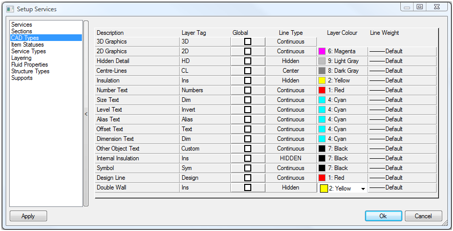
The table below shows an explanation of each description. Each item is processed individually as it is drawn, so not all of the options below apply to every item.
| Description | Layer Tag | Explanation |
| 3D Graphics | 3D | Defines the layer that the main part of the item is drawn on. |
| 2D Graphics | 2D | Defines the layer that graphical symbol component of an item will be drawn on e.g. attenuators, fire dampers, air handling units and diffusers). |
| Hidden Detail | HD | Defines the layer that the Hidden detail component of an item will be drawn on. |
| Center-Lines | CL | Defines the layer that the center lines of circular items will be drawn on. |
| Insulation | Ins | Defines the layer that the items Insulation annotation is drawn on. |
| Number Text | Numbers | Defines the layer that the Item Numbers annotation is drawn on. |
| Size Text | Dim | Defines the layer that the Dimension annotation is drawn on. |
| Level Text | Invert | Defines the layer that the Levels annotation is drawn on. |
| Alias Text | Alias | Defines the layer that the Alias annotation is drawn on. |
| Offset Text | Text | Defines the layer that the Offset annotation is drawn on. |
| Dimension Text | Dim | Defines the layer that the Dimension annotation is drawn on. |
| Other Object Text | Custom | Defines the layer that the Other Object annotation is drawn on. |
| Internal Insulation | Ins | Defines the layer that the Internal Insulation is drawn on. |
| Symbol | Sym | Defines the layer that the Symbol is drawn on. |
| Design Line | Design | Defines the layer that the Design Line is drawn on. |
| Double Wall | Ins | Defines the layer that the Double Wall is drawn on. |
To Create Global Layer Names:
This example explains how Global Layer names are created. On the CAD Type tab, there is a Global column. Any number of the CAD Types can be designated Global Layer Names by ticking the box in this column.

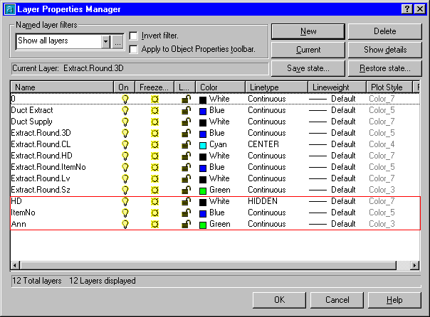
In this example, Hidden Detail, Number Text and Size text have all been selected. This means that just the CAD Type Layer Tag becomes the layer name for these particular CAD Types. So, for example with the Global box selected for Number Text, it would no longer have the Layer Name Extract.Round.ItemNo. Instead it would be ItemNo.
Using the above example the other Layer Names would be created as: Hidden Detail - HD Size Text - Ann
Extract from Layer database. Three new layers have been added to the bottom of the list: